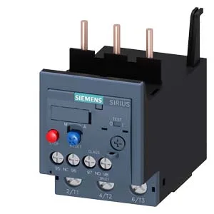
Siemens 3RU2136-4FB0-ZX95 — Overload Relays

Siemens 3RU2136-4FB0-ZX95 thermal overload relay, S2, CLASS

MPN3RU2136-4FB0-ZX95

Siemens SIRIUS 3RU2136-4FB0-ZX95 thermal overload relay, Size S2, CLASS 10, 18.5 kW at 400 V, 690 V rated, screw terminals, auxiliary contacts rated 2 A at 24 V.

Source DocumentedChannel stated on listing & quote
Condition PhotosReal unit photos / video on request
WhatsApp AnswersFast human replies for machine-down parts
Worldwide DispatchDHL/FedEx — transit quoted per order
Independent China distributor & sourcing agent· Listing updated Sep 2026

Specifications

3RU2136-4FB0-ZX95 — Identification
ParameterValue
Product brand nameSIRIUS
Product designationthermal overload relay
Frame size (overload relay)S2
Combinable contactor sizesS2
Reference code (IEC 81346-2)F
3RU2136-4FB0-ZX95 — Protection & Trip
ParameterValue
Overload current setting range28 ... 40 A
Trip classCLASS 10
Overload release typethermal
3RU2136-4FB0-ZX95 — Electrical (main circuit)
ParameterValue
Rated operational current40 A
Poles (main circuit)3
Rated operating frequency50 ... 60 Hz
Rated insulation voltage (AC, pollution degree 3)690 V
Rated value (AC-3e), max.690 V
Rated surge withstand voltage6 kV
Main current circuitscrew-type terminals
Power loss at rated current (hot)15.6 W
Per pole5.2 W
3RU2136-4FB0-ZX95 — Auxiliary contacts
ParameterValue
Auxiliary contacts: NO1
Auxiliary contacts: NC1
Auxiliary contacts: CO (changeover)0
Auxiliary switch short-circuit protection (required fuse)fuse gG: 6 A, quick: 10 A
Switching current at 24 V2 A
Switching current at 60 V0.3 A
Switching current at 110 V0.22 A
Switching current at 120 V3 A
Switching current at 125 V0.22 A
Switching current at 220 V0.11 A
Switching current at 230 V2 A
Switching current at 400 V1 A
3RU2136-4FB0-ZX95 — Connection & Mounting
ParameterValue
Mounting / fastening methodContactor mounting
Mounting positionany
Main-circuit connector arrangementTop and bottom
Auxiliary/control circuit connection typescrew-type terminals
Removable aux./control terminalNo
Conductor cross-section: solid or stranded2x (0.5 ... 1.5 mm²), 2x (0.75 ... 2.5 mm²)
Conductor cross-section: finely stranded with ferrule2x (0.5 ... 1.5 mm²), 2x (0.75 ... 2.5 mm²)
3RU2136-4FB0-ZX95 — Environmental
ParameterValue
Operating temperature-40 ... +70 °C
Storage temperature-55 ... +80 °C
Transport temperature-55 ... +80 °C
Relative humidity, operating10 ... 95 %
Max. installation altitude2 000 m
3RU2136-4FB0-ZX95 — Mechanical
ParameterValue
Width55 mm
Height90 mm
Depth105 mm

Product details

It mounts directly to a contactor via the contactor mounting fastening method, making it a compact, integrated motor starter component for a control panel. The thermal overload release design means it uses a bimetallic strip that heats up and trips based on motor current, providing inverse-time protection. The auxiliary switch is integrated into the relay body, with contacts rated for pilot duty across common control voltages: 2 A at 24 V, 3 A at 120 V, 2 A at 230 V, 1 A at 400 V, and 0.75 A at 690 V. The note "for message 'Tripped'" indicates this auxiliary contact signals the tripped state back to the PLC or annunciator.

Ratings and fit for motor protection

This relay is rated for motors up to 18.5 kW at 400 V, 22 kW at 500 V, and 37 kW at 690 V. For North American applications, it carries current ratings of 40 A at both 480 V and 600 V. The maximum AC-3e rated voltage is 690 V, covering most low-voltage industrial motor circuits. Power dissipation per pole is 5.2 W, which matters for thermal management inside a sealed enclosure — three poles at full load add 15.6 W of heat that must be considered in the panel cooling calculation. The relay operates from -40 to +70 °C during operation, with temperature compensation active from -40 to +60 °C, ensuring accurate tripping regardless of ambient temperature shifts in an outdoor or unconditioned enclosure.

Physical dimensions are 55 mm wide, 90 mm high, and 105 mm deep — the S2 form factor fits standard Siemens contactor footprints. Mounting position is any orientation, giving flexibility in dense panel layouts. Main contacts use screw-type terminals accepting 2x (0.5 to 1.5 mm²) or 2x (0.75 to 2.5 mm²) solid or stranded wire. The screw size for main contacts is M6. Use a Pozidriv PZ 2 screwdriver tip with shaft diameter 5 to 6 mm for termination.

Substance prohibitance date is October 15, 2014, aligning with RoHS compliance requirements for the European market. This confirms the part meets the restricted substance limits effective from that date.

Frequently asked questions

What is the trip class and what does it mean?

It is CLASS 10, meaning the relay will trip within 10 seconds at 7.2 times the set current. This suits standard induction motor starting without nuisance tripping.

What are the auxiliary contact ratings?

The integrated auxiliary switch is rated 2 A at 24 V, 3 A at 120 V, 2 A at 230 V, 1 A at 400 V, and 0.75 A at 690 V. The function is for signaling the tripped condition.

What is the maximum motor power it can protect?

It is rated for motors up to 18.5 kW at 400 V, 22 kW at 500 V, and 37 kW at 690 V. At 480 V and 600 V it carries 40 A.

What are the physical dimensions?

The relay measures 55 mm wide, 90 mm high, and 105 mm deep (Size S2). It mounts directly to a contactor and can be installed in any orientation.

Does this relay comply with RoHS?

Yes, the substance prohibitance date of October 15, 2014 confirms RoHS compliance for restricted substances.

MPN
3RU2136-4FB0-ZX95