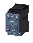
Siemens 3RU2136-4FB1 — Overload Relays

Siemens 3RU2136-4FB1 SIRIUS Overload Relay, CLASS 10

MPN3RU2136-4FB1
Active

Siemens SIRIUS 3RU2136-4FB1 thermal overload relay, S2 frame size, CLASS 10 trip class, 18.5 kW at 400 V, 37 kW at 690 V, screw-type terminals, integrated auxiliary switch with message 'Tripped'.

$59.69Ref. price · indicative, final on quote
StockContact for availability
Lead timeIn Stock wk
MOQ1 pcs
Sourced new & surplus through independent channelsAuthenticity-screened · ESD-safe packingListing updated Jul 2026
How we verify every order →

Specifications

Identification

3RU2136-4FB1 — Identification
ParameterValue
Product brand nameSIRIUS
Product designationthermal overload relay
Frame size (overload relay)S2
Combinable contactor sizesS2
Reference code (IEC 81346-2)F

Protection & Trip

3RU2136-4FB1 — Protection & Trip
ParameterValue
Overload current setting range28 ... 40 A
Trip classCLASS 10
Overload release typethermal

Electrical (main circuit)

3RU2136-4FB1 — Electrical (main circuit)
ParameterValue
Rated operational current40 A
Poles (main circuit)3
Rated operating frequency50 ... 60 Hz
Rated insulation voltage (AC, pollution degree 3)690 V
Rated value (AC-3e), max.690 V
Rated surge withstand voltage6 kV
Main current circuitscrew-type terminals
Power loss at rated current (hot)15.6 W
Per pole5.2 W

Auxiliary contacts

3RU2136-4FB1 — Auxiliary contacts
ParameterValue
Auxiliary contacts: NO1
Auxiliary contacts: NC1
Auxiliary contacts: CO (changeover)0
Auxiliary switch short-circuit protection (required fuse)fuse gG: 6 A, quick: 10 A
Switching current at 24 V2 A
Switching current at 60 V0.3 A
Switching current at 110 V0.22 A
Switching current at 120 V3 A
Switching current at 125 V0.22 A
Switching current at 220 V0.11 A
Switching current at 230 V2 A
Switching current at 400 V1 A

Connection & Mounting

3RU2136-4FB1 — Connection & Mounting
ParameterValue
Mounting / fastening methodstand-alone installation
Mounting positionany
Main-circuit connector arrangementTop and bottom
Auxiliary/control circuit connection typescrew-type terminals
Removable aux./control terminalNo
Conductor cross-section: solid or stranded2x (0.5 ... 1.5 mm²), 2x (0.75 ... 2.5 mm²)
Conductor cross-section: finely stranded with ferrule2x (0.5 ... 1.5 mm²), 2x (0.75 ... 2.5 mm²)
Conductor range (AWG), auxiliary contacts2x (20 ... 16), 2x (18 ... 14)

Environmental

3RU2136-4FB1 — Environmental
ParameterValue
Operating temperature-40 ... +70 °C
Storage temperature-55 ... +80 °C
Transport temperature-55 ... +80 °C
Relative humidity, operating10 ... 95 %
Max. installation altitude2 000 m

Mechanical

3RU2136-4FB1 — Mechanical
ParameterValue
Width55 mm
Height105 mm
Depth117 mm

Product details

CLASS 10 trip coordination

The 3RU2136-4FB1: This sets the coordination window with the upstream MCCB — a Type 1 or Type 2 coordination study needs this number to verify the breaker clears before the relay damage curve is exceeded. The relay's thermal memory prevents immediate restart after a trip, protecting the motor winding from repeated locked-rotor events.

S2 frame mounting and wiring

S2 frame size, 117 mm depth, 55 mm width, 105 mm height — mounts standalone on the panel backplate or directly to the matching SIRIUS contactor. Any mounting position is allowed, and temperature compensation is active from -40 °C to +60 °C, so the trip accuracy holds regardless of orientation or ambient conditions inside the enclosure.

Auxiliary contact and signalling

This contact signals the PLC or HMI that the relay has operated, so the control logic can sequence a restart or trigger an alarm without waiting for a manual reset.

The relay is RoHS compliant per the substance prohibitance date of 10/15/2014. Power dissipation is 5.2 W per pole at rated current — account for this in the enclosure thermal budget, especially in a multi-relay panel with restricted airflow.

Frequently asked questions

What motor power does 3RU2136-4FB1 cover at 400 V?

Rated for 18.5 kW at 400 V and 37 kW at 690 V, making it suitable for standard European motor sizes in those voltage tiers.

What does the 'Tripped' message contact do on 3RU2136-4FB1?

The integrated auxiliary switch provides a 'Tripped' signal contact rated 2 A at 24 V, 3 A at 120 V, and 2 A at 230 V. It closes when the relay operates, giving the PLC or HMI a discrete input that the overload has tripped.

MPN
3RU2136-4FB1