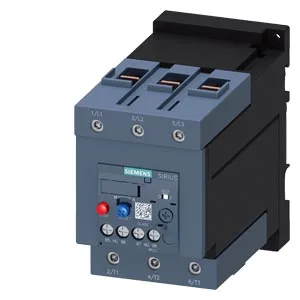
The 37 kW at 400 V rated value and 65 A at 480 V rated value define the maximum motor power and full-load current the relay can protect at those voltages; match these to your motor nameplate, not the contactor rating. The relay mounts standalone (fastening method: stand-alone installation) in any position, so panel integration is flexible — no forced orientation.
Key specs that decide the wiring and panel fit
Terminals are screw-type for the main current circuit, accepting solid conductors 2x (2.5... 16 mm²) and stranded 2x (6... 16 mm²), 2x (10... 50 mm²), or 1x (10... 70 mm²). The screwdriver drive is a 4 mm hexagon socket — no Phillips or slotted head, so have the correct bit on hand. Auxiliary contacts are integrated, rated at 2 A at 24 V, 3 A at 120 V, 2 A at 230 V, and 1 A at 400 V. Temperature compensation is active from -40 to +60 °C, with operating range -40 to +70 °C. During operation, the relay dissipates 6.3 W per pole.
What the Note for message Tripped means
The evidence lists a Note for message Tripped. This is the diagnostic signal the relay sends when it has operated — a tripped-state indication that can be wired into a PLC or control system to trigger an alarm or shutdown sequence. It is not a fault code; it is a binary status output that confirms the relay has opened the motor circuit due to overload or phase loss.