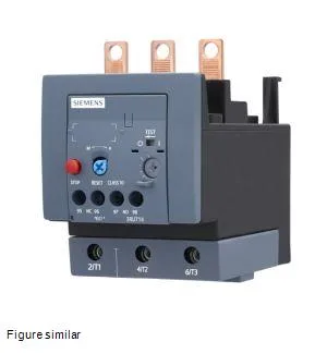
Siemens 3RU7146-4MB0 — Overload Relays

Siemens 3RU7146-4MB0 SIRIUS Thermal Overload Relay, 100 A, C

MPN3RU7146-4MB0

Siemens SIRIUS 3RU7146-4MB0, Size S3 thermal overload relay, 100 A rated operational current, Class 10 trip class, screw terminals, contactor mounting.

Source DocumentedChannel stated on listing & quote
Condition PhotosReal unit photos / video on request
WhatsApp AnswersFast human replies for machine-down parts
Worldwide DispatchDHL/FedEx — transit quoted per order
Independent China distributor & sourcing agent· Listing updated Sep 2026

Specifications

3RU7146-4MB0 — Identification
ParameterValue
Product brand nameSIRIUS
Product designationThermal overload relay
Frame size (overload relay)S3
Combinable contactor sizesS3
3RU7146-4MB0 — Protection & Trip
ParameterValue
Overload current setting range80 ... 100 A
Trip classCLASS 10
Overload release typethermal
3RU7146-4MB0 — Electrical (main circuit)
ParameterValue
Rated operational current100 A
Poles (main circuit)3
Rated operating frequency50 ... 60 Hz
Rated insulation voltage (AC, pollution degree 3)1 000 V
Rated surge withstand voltage8 kV
Main current circuitscrew-type terminals
Power loss at rated current (hot)21 W
Per pole7 W
3RU7146-4MB0 — Auxiliary contacts
ParameterValue
Switching current at 24 V3 A
Switching current at 230 V2 A
3RU7146-4MB0 — Connection & Mounting
ParameterValue
Mounting / fastening methodContactor mounting
Mounting positionwith vertical mounting surface +/-135° rotatable, with vertical mounting surface +/- 45° tiltable to the front and back
Main-circuit connector arrangementTop and bottom
Auxiliary/control circuit connection typescrew-type terminals
Conductor cross-section: solid or stranded2x (0.5 ... 1.5 mm²), 2x (0.75 ... 2.5 mm²)
Conductor cross-section: finely stranded with ferrule2x (0.5 ... 1.5 mm²), 2x (0.75 ... 2.5 mm²)
3RU7146-4MB0 — Environmental
ParameterValue
Operating temperature-20 ... +55 °C
Transport temperature-25 ... +70 °C
Relative humidity, operating0 ... 90 %
Max. installation altitude2 000 m
3RU7146-4MB0 — Mechanical
ParameterValue
Width70 mm
Height120 mm
Depth140 mm

Product details

The thermal bimetallic design responds to motor heating, not just instantaneous current, so it tracks the actual thermal state of the windings. The relay mounts directly onto a SIRIUS S3 contactor (the same frame size), forming a compact motor starter package on the DIN rail. The front panel carries an IP20 rating — safe for finger contact in an open panel — while the terminal area is IP00, meaning the wiring zone expects enclosure protection. Screw-type terminals on both the main and auxiliary circuits accept 2× (0.5…1.5 mm²) solid or 2× (0.75…2.5 mm²) stranded, torqued to 4…6 N·m on the mains and 0.8…1.2 N·m on the auxiliaries.

Deployment context

The auxiliary contact set includes a normally-open and normally-closed pair; the DC-13 rating of 1 A at 24 V means those contacts can switch PLC inputs or relay coils in a 24 VDC control loop without derating. Mounting position is flexible: the relay can be rotated ±135° on a vertical surface or tilted ±45° front-to-back, which helps when fitting into tight enclosures or angled subpanels. A 6 mm air gap to grounded parts at the side is required — standard for 1 000 V rated insulation. The 21 W typical power loss at rated current means the enclosure's thermal budget must account for that heat, especially when multiple starters are ganged.

Frequently asked questions

What does the Class 10 trip class mean for motor protection?

Class 10 means the relay will trip within 10 seconds at 7.2 times the current setting. This is fast enough to protect standard induction motors during a locked-rotor condition while allowing normal starting inrush — a common choice for general-purpose motor starters.

What contactor does this relay mount to?

It mounts directly onto a SIRIUS Size S3 contactor (same frame size designation) using the contactor mounting method. No separate DIN-rail adapter is needed — the relay clips onto the contactor and connects the main circuit through the contactor's load-side terminals.

What are the terminal specifications for wiring?

The main circuit terminals accept 2× (0.5…1.5 mm²) solid or 2× (0.75…2.5 mm²) stranded wire, torqued to 4…6 N·m. Auxiliary terminals take the same wire sizes but torque to 0.8…1.2 N·m. All terminals are screw-type.

MPN
3RU7146-4MB0