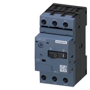
Siemens 3RV1011-1DA10 — Motor Protection Circuit Breakers (MPCB)

Siemens 3RV1011-1DA10 SIRIUS Motor Protection Circuit Breake

MPN3RV1011-1DA10
Active

Siemens SIRIUS 3RV1011-1DA10, motor protection circuit breaker, Class 10, 100 kA breaking capacity at 400 V, screw-type terminals, snap-on DIN rail mount.

$83.33Ref. price · indicative, final on quote
Source DocumentedChannel stated on listing & quote
Condition PhotosReal unit photos / video on request
WhatsApp AnswersFast human replies for machine-down parts
Worldwide DispatchDHL/FedEx — transit quoted per order
Independent China distributor & sourcing agent· Listing updated Sep 2026

Specifications

3RV1011-1DA10 — Identification
ParameterValue
SeriesSIRIUS
Product designationCircuit breaker
Frame sizeS00
3RV1011-1DA10 — Electrical
ParameterValue
Rated operational current (Ie)3.2 A
Rated voltage20 ... 690 V
Rated voltage, AC-3 (max.)690 V
Rated frequency50 ... 60 Hz
Rated insulation voltage (Ui), pollution degree 3690 V
Rated impulse withstand voltage (Uimp)6 kV
Number of poles3
Power loss (AC, hot)7.25 W
Power loss, per pole (AC, hot)2.4 W
3RV1011-1DA10 — Protection & Tripping
ParameterValue
Overload release setting range2.2 ... 3.2 A
Instantaneous short-circuit trip current42 A
Trip classCLASS 10
Breaking capacity at 240 V (AC)100 kA
Breaking capacity at 400 V (AC)100 kA
Breaking capacity at 500 V (AC)3 kA
Breaking capacity at 690 V (AC)2 kA
Breaking capacity at 240 V100 kA
Breaking capacity at 690 V2 kA
Short-circuit trip typemagnetic
Overload release typethermal
Short-circuit protectionYes
Phase-failure detectionYes
Ground-fault detectionNo
Auxiliary switch extendableYes
3RV1011-1DA10 — Endurance & Switching
ParameterValue
Endurance, main contacts (typ.)100 000
Endurance, auxiliary contacts (typ.)100 000
Switching frequency, AC-3 (max.)15 1/h
Auxiliary CO (changeover) contacts0
3RV1011-1DA10 — Connections
ParameterValue
Main-circuit terminal typescrew-type terminals
Main-circuit connector arrangementTop and bottom
Conductor cross-section, solid / stranded2x (0.5 ... 1.5 mm²), 2x (0.75 ... 2.5 mm²)
Conductor cross-section, finely stranded with ferrule2x (0.5 ... 1.5 mm²), 2x (0.75 ... 2.5 mm²)
3RV1011-1DA10 — Mechanical
ParameterValue
Height90 mm
Width45 mm
Depth75 mm
Mounting methodscrew and snap-on mounting onto 35 mm DIN rail according to DIN EN 60715
Mounting positionany
3RV1011-1DA10 — Environmental
ParameterValue
Operating temperature-20 ... +60 °C
Storage temperature-50 ... +80 °C
Transport temperature-50 ... +80 °C
Relative humidity (operation)10 ... 95 %
Max. installation altitude2 000 m
3RV1011-1DA10 — Specifications
ParameterValue
Design Of The ProductFor motor protection

Product details

The interrupting rating is 100 kA at both 240 V and 400 V. At 690 V the breaking capacity drops to 2 kA, and at 500 V to 3 kA. The rated operational voltage spans 20 to 690 V, covering most low-voltage industrial systems from control transformers up to 690 V line supplies. The -20 °C lower limit means it is not rated for freezer or arctic outdoor applications without a heated enclosure.

The 45 mm width (three module spaces) and 75 mm depth fit standard distribution boards and motor control center buckets. Clearance requirements: 20 mm upwards, 20 mm downwards, 9 mm to the side, and zero forwards or backwards. That 9 mm side clearance is tight — adjacent devices must not overhang or you lose access to the screw terminals. Screw-type terminals on the main circuit accept two conductors: 2×(0.5...1.5 mm²) or 2×(0.75...2.5 mm²) solid or stranded. The M3 screw size is standard for this current class; use a PZ1 bit and torque to 0.8–1.2 Nm per Siemens installation instructions.

For BOM freeze or long-term project planning, the current status means you can specify this part without an obsolescence risk in the near term. The SIRIUS platform is a mature, widely deployed family, so field-proven reliability is well documented.

Frequently asked questions

What is the breaking capacity at different voltages?

The interrupting rating is 100 kA at 240 V and at 400 V. At 500 V it is 3 kA, and at 690 V it is 2 kA. For 690 V installations, verify the available fault current is below 2 kA or use a current-limiting upstream device.

What is the trip class and what does it mean?

It is Class 10, meaning it will trip within 10 seconds at 7.2 times the rated current. This is the standard for protecting standard induction motors during start-up — fast enough to prevent thermal damage, slow enough to ride through motor inrush without nuisance tripping.

What clearance is needed around this breaker in a panel?

Clearance requirements: 20 mm upwards, 20 mm downwards, 9 mm to the side, and zero forwards or backwards. The 9 mm side clearance is tight — adjacent devices must not overhang or you lose access to the screw terminals.

Does it detect phase failure?

Yes, phase failure detection is built in. A loss of one phase will cause the breaker to trip, preventing single-phasing damage to the motor winding.

MPN
3RV1011-1DA10