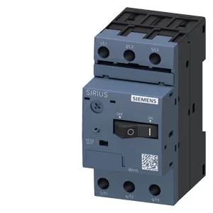
It combines overload protection (Class 10 trip curve) with short-circuit interruption, rated for 100 kA breaking capacity at both 240 V and 400 V. No ground fault detection on this variant. That is the standard for standard-duty motor starting — not for high-inertia loads like crushers or centrifuges, which need Class 20 or 30. For a pump, fan, compressor, or conveyor drive, Class 10 is what the motor winding insulation expects.
That is the standard DIN-rail profile found in every industrial control panel. Mounting position is any orientation. Clearance requirements: 20 mm upward, 20 mm downward, 9 mm to the side, zero forward or backward. That 9 mm side gap is tight — adjacent devices must respect it, or the arc-chamber venting and conductor bending space is compromised.
Breaking capacity and short-circuit coordination
For most 400 V industrial distribution (where prospective fault current is typically 25–65 kA), the 100 kA figure gives plenty of SCCR headroom. The required backup fuse varies by voltage: at 240 V none required; at 400 V use gL/gG 40 A; at 500 V or 690 V use gL/gG 35 A.
Main current circuit terminals are screw-type, size M3. Accepts two conductors per terminal: 2 × (0.5 to 1.5 mm²) solid or stranded, or 2 × (0.75 to 2.5 mm²). That is standard for motor branch circuits up to the rated current of this frame.