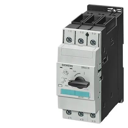
Breaking capacity is rated at 100 kA at 240 V AC, 50 kA at 400 V, 10 kA at 500 V, and 4 kA at 690 V. For applications requiring ground fault protection, an external module or residual current device must be added downstream.
Zero clearance required at the back and sides — 0 mm backwards, 0 mm at the side — so it can be packed tightly against adjacent devices on the rail without derating for airflow. Dimensions: 55 mm wide × 140 mm high × 149 mm deep. The 55 mm width is three 18 mm module spaces, so it occupies three positions on a standard DIN-rail terminal block layout.
Terminal Specifications and Wiring
Main current circuit uses screw-type box terminals. Accepts solid conductors 2× (0.75…16 mm²) and stranded conductors 2× (0.75…25 mm²) or 1× (0.75…35 mm²). AWG equivalents: 2× (18…2) for solid, 2× (18…2) or 1× (18…2) for stranded. Finely stranded with core-end processing: 2× (0.75…16 mm²) or 0.75…25 mm². Auxiliary and control circuit also uses screw-type terminals.
Shock resistance: 25g for 11 ms. Protection class on the front: IP20 — suitable for enclosure use where no water ingress is expected. Power dissipation: 29 W total in hot operating state, 9.7 W per pole. This matters for thermal management inside a sealed enclosure — at full load, expect nearly 30 W of heat to be dissipated.
Substance prohibition date of 07/01/2006 indicates RoHS compliance from that date forward. Surge voltage resistance rated at 6000 V, which aligns with IEC 60947-2 overvoltage category III requirements for industrial control panels.