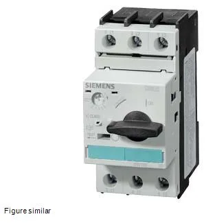
Rated continuous current is 1.6 A at 400 V, with a symmetrical breaking capacity of 100 kA across the full AC voltage range — 240 V, 400 V, 500 V, and 690 V — so it can safely interrupt a fault up to 100 kA without upstream cascading, provided the prospective short-circuit current at the installation point stays within that limit.
Mounts via screw or snap-on onto 35 mm standard mounting rail per DIN EN 50022 — the 45 mm width and 97 mm height fit a standard 45 mm module footprint, leaving 0 mm clearance needed at the back or sides for heat dissipation, so it can be packed tightly in a multi-row enclosure. Depth is 96 mm from the rail base to the front of the terminals — account for this when laying out gland plates and door clearance; the screw-type main circuit terminals accept 2x (0.25 to 2.5 mm²) solid or 2x (24 to 14 AWG) conductors, so standard control wiring fits without adapters.
Auxiliary contact and switching ratings
An integrated auxiliary switch is transverse in design — rated 1 A at 24 V, 0.15 A at 60 V, and 0.5 A at 230 V — these are the switching capacities for the auxiliary contact, not the main circuit; use them for status feedback to a PLC or to drive a remote indicator, but stay within the voltage-specific current limits to avoid contact welding. Maximum switching frequency in AC-3 duty is 15 operations per hour — this is a protection device, not a contactor for repetitive cycling; the mechanical endurance of the main contacts is rated at 100,000 operations typical.
Operating ambient temperature range is -20 to +60 °C, storage and transport range is -50 to +80 °C — the wider storage range governs handling, not running; shock resistance is 25 g for 11 ms, so it survives typical panel transit vibration.