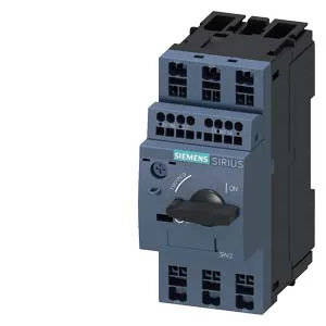
This is a high-fault rating for a 45 mm wide device, meaning it can be used on strong utility feeds without requiring a current-limiting upstream fuse or breaker in most installations. It includes phase failure detection, so if one phase drops out, the breaker trips — protecting the motor from single-phasing. There is no ground fault detection built in; that would require an additional module or a separate ground-fault relay. The auxiliary contact ratings cover multiple control voltages: 1 A at 24 V, 0.5 A at 120/125/230 V, and 0.15 A at 60 V. The main circuit voltage range is 20 to 690 V, covering most global low-voltage motor systems.
The 45 mm width (three module spaces) is standard for this class of motor protection breaker. Depth is 97 mm, height 106 mm — check these against your enclosure depth and door clearance. Clearance requirements: 50 mm above and below, 30 mm at the sides, 0 mm forward and backward. This keeps heat dissipation adequate and allows arc-quenching space. Terminals are spring-loaded, accepting 2× (0.5 to 2.5 mm²) solid or stranded wire. No screw torque to verify, but strip length and ferrule size matter — standard practice for spring-cage terminations.
Lifecycle and sourcing position
No successor part number has been announced. If you are kitting a new panel design, this part number is stable for the foreseeable future.
How this compares to the 3RV2011-0BA20
The 3RV2011-0BA20 is the closest functional sibling — same 45 mm width, same DIN rail mount, same Trip Class 10, same 100 kA breaking capacity. The difference is in the auxiliary contact configuration and the thermal setting range. The -0FA25 variant carries specific auxiliary contact ratings (1 A at 24 V, 0.5 A at 230 V) that the -0BA20 may not match exactly. If your control voltage is 24 VDC and you need the 1 A rating, the -0FA25 is the correct choice. The -0BA20 would require checking its auxiliary contact specs against your load.