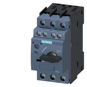
The Siemens SIRIUS 3RV2021-4DA15-ZX95 is a motor protection circuit breaker designed for Class 10 trip characteristics, meaning it will trip within 10 seconds at 7.2× the thermal setting — the standard for standard-duty induction motor starting where the rotor is not stalled during acceleration. It carries a 25 kA breaking capacity at 400 V, which is the figure that governs fault interruption in a 400 V distribution panel; the 100 kA rating at 240 V is relevant only for the North American split-phase context.
Depth of 97 mm and height of 97 mm mean it projects about 97 mm forward from the rail; verify gland-plate depth if the enclosure is shallow.
Breaking capacity and backup fusing
The interrupting ratings span the common industrial voltages: 100 kA at 240 V, 25 kA at 400 V, 5 kA at 500 V, and 2 kA at 690 V. The 25 kA at 400 V is the one that matters for most European and Asian 400 V line-side faults; the 690 V rating drops to 2 kA, so if the supply transformer secondary is 690 V, verify the available fault current is below that. For backup protection by upstream fuses, the maximum fuse ratings are gL/gG 63 A at 400 V, 50 A at 500 V, and 50 A at 690 V — these are the fuse sizes that coordinate with the breaker's let-through energy.
The auxiliary contact block (integrated or add-on, depending on variant) is rated 1 A at 24 V, 0.5 A at 120 V, 0.5 A at 125 V, 0.5 A at 230 V, and 0.15 A at 60 V. These are the maximum continuous currents the auxiliary contacts can switch; for a PLC input at 24 V, the 1 A rating is generous, but for a 230 V control relay coil, the 0.5 A limit means the coil inrush must stay under that. Terminal capacity for the main contacts is M4 screws, accepting 2×(0.5…1.5 mm²) or 2×(0.75…2.5 mm²) solid or stranded.