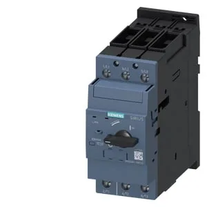
The 55 mm width and 149 mm depth are the critical dimensions for panel layout — a standard 600 mm deep enclosure leaves roughly 450 mm of wiring space behind the rail. Any mounting position is permitted, so vertical or horizontal rail orientation is fine.
The interrupting capacity varies by system voltage: 100 kA at 240 V, 30 kA at 400 V, 5 kA at 500 V, and 2 kA at 690 V. At 400 V — the most common industrial distribution voltage — the 30 kA rating means this breaker is suitable for installations with a transformer rating up to about 2 MVA (assuming 6% impedance).
Main circuit terminals are screw-type, accepting 2x 1–25 mm² or 1x 1–35 mm² solid or stranded copper. The M6 main contact studs are sized for the full rated current. No ground-fault or phase-failure detection is built in — those functions would need to be handled upstream or by an external relay.