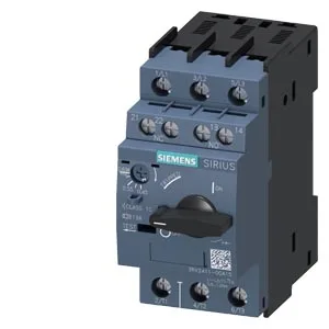
Product identity and deployment context
Rated for a supply voltage range of 20... 690 V, it delivers a breaking capacity of 100 kA at 400 V, 500 V, and 690 V, and also at 240 V. Trip class is CLASS 10, which defines the maximum permissible trip time under locked-rotor conditions — 10 seconds at 7.2× Ie per IEC 60947-4-1. This is the standard thermal overload class for standard-duty motor and transformer starting applications; it coordinates with downstream contactors without nuisance tripping during inrush.
For transformer primary protection, phase-loss response is essential — a single-phased transformer draws high currents on the remaining phases, and this breaker will trip on the thermal curve. Ground fault protection would need an external residual-current device. The auxiliary circuit ratings are specified per voltage: 1 A at 24 V, 0.5 A at 120/125/230 V, and 0.15 A at 60 V. These are the switching capacities for the internal auxiliary contacts (e.g., for signaling or interlocking). For audit purposes, verify that the connected load (PLC input, relay coil) does not exceed these values at the applied control voltage. The wider storage limit governs handling, not running — the breaker can be warehoused in unheated conditions but must not be energized outside the operating band.
Clearance distances: 50 mm upwards and downwards, 30 mm at the side, 0 mm forwards and backwards. These are the minimum free air gaps needed around the arc chute for safe fault interruption; crowding the breaker against the enclosure wall or other devices voids the breaking capacity rating. Dimensions: 97 mm depth, 45 mm width, 97 mm height. The 45 mm width (3 module spaces on a 15 mm pitch DIN rail) is a standard footprint for this class of motor-protective circuit breaker. Main contact terminals accept 2x (0.5... 1.5 mm²) solid or stranded, or 2x (0.75... 2.5 mm²) — screw-type terminals with M3 thread for the main contacts.