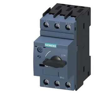
Rated breaking capacity at 240 V AC is 100 kA, dropping to 30 kA at 400 V AC, 5 kA at 500 V AC, and 2 kA at 690 V AC. For AC-side faults, the figures are 100 kA at 240 V AC, 55 kA at 400 V AC, 10 kA at 500 V AC, and 4 kA at 690 V AC. These numbers tell you where this breaker can sit in a distribution hierarchy: at 400 V it handles a 30 kA prospective fault current, which covers most industrial panelboards fed by a transformer of moderate size. At 690 V the 2 kA rating limits it to low-fault-current branches or downstream of a current-limiting device.
Dimensions are 97 mm deep, 45 mm wide, 97 mm tall — the 45 mm width is a single modular unit, so it occupies one 45 mm slot on the rail. Clearance: 50 mm upward, 50 mm downward, 30 mm to the side, zero forward or backward. Any mounting position is allowed. The S00 frame size means it fits alongside other S00 accessories (auxiliary switches, shunt trips) on the same DIN rail without extra adapters.
Main circuit terminals are screw-type, accepting 2× (0.75 to 2.5 mm²) solid or stranded, or 2× 4 mm². Screwdriver shaft diameter must be 5 to 6 mm. Terminal screws are M3. These are standard panel-building sizes — no special crimp tools needed, but the 4 mm² capacity means you can land a single larger conductor if you parallel the two ports.
Environmental and operating limits
The wide cold end (-50 °C) is unusual for a molded-case breaker — it means this part can live in an unheated enclosure in a cold climate without derating for low ambient. The rated insulation voltage is 20 to 690 V, covering standard low-voltage systems up to 690 V phase-to-phase.