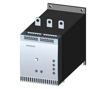
162 A at 40°C — what it means for your motor load
The 3RW4056-2BB35: That temperature derating curve is the real limit for panel placement — if your enclosure runs hot, the usable current falls fast.
Thyristor switching and adjustable current limit
Solid-state thyristors handle the motor inrush — no contact wear, so it's suited for frequent starts. The adjustable current limitation lets you set the start current below the full-load rating, which protects both the motor and the downstream wiring during acceleration. Minimum load is 20% of the rated current, so it won't regulate properly on very small motors — size the starter to the motor FLA, not the panel rating.
Panel fit and mounting constraints
Size S6 frame: 198 mm high, 120 mm wide, 250 mm deep. Screw fixing to the back panel — no DIN rail snap-on. Clearance: 100 mm above, 75 mm below, 5 mm at the sides. That side gap is tight; plan your gland plate and cable routing accordingly. Mounting position depends on the fan option: with the additional fan, the unit can be mounted vertical with ±90° rotation and ±22.5° tilt front/back; without the fan, only ±10° rotation and ±10° tilt. If your panel has airflow constraints, the fan version buys more orientation flexibility.
Wiring terminals and conductor sizes
The main contact wire range also covers 4–250 kcmil. Auxiliary contacts accept 2x (24–16 AWG). Maximum motor cable length is 300 m — beyond that, capacitive charging current can cause nuisance tripping or reduce start torque.
Environmental and compliance ratings
Pollution degree 3 per IEC 60947-4-2 — suitable for industrial environments with conductive dust or occasional condensation. Operating temperature -25 to +60°C, storage -40 to +80°C. Insulation voltage rated 600 V.