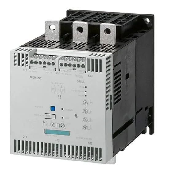
280 A continuous — the rating that sizes the motor branch
The 3RW4074-2BB35: That 280 A figure is the base continuous current that sizes the motor branch — the contactor, overload relay, and cable all follow from it. The 600 V insulation voltage sets the system voltage ceiling; the 50/60 Hz operating frequency covers global line frequencies without a hardware change. Motor overload protection is built in, and the adjustable current limitation lets you tune the starting current to the load — useful for pumps or conveyors where a hard start stresses the drivetrain. The minimum load is 20 %, so it handles lightly loaded motors without tripping on undercurrent.
Panel fit — Size S12, busbar connection, 115 V control
The S12 frame measures 278 mm deep, 160 mm wide, and 230 mm high. Screw fixing to the mounting surface — no DIN rail clip. The main current circuit uses busbar connection with a clamping range of 2/0 to 500 kcmil using both clamping points, or 250 to 500 kcmil at the back point and 3/0 to 600 kcmil at the front. Stranded wire for the main circuit is 70 to 240 mm²; finely stranded 50 to 240 mm². Auxiliary contacts accept 2x (24 to 16) AWG; solid wire for aux circuits is 2x (0.25 to 1.5 mm²). The maximum wire length to the motor is 300 m — keep that in mind for remote motor installations where voltage drop matters.
Ambient and mounting constraints
The derating temperature is 40 °C — above that, the continuous current drops as shown in the derating steps. Mounting position: with an additional fan, the unit can be mounted on a vertical surface with +/-90° rotation and +/-22.5° tilt front/back. Without the fan, rotation is limited to +/-10° and tilt to +/-10°. Clearances: 100 mm upward, 75 mm downward, and 5 mm at the sides. The side clearance is tight — plan the gland plate and busbar routing accordingly.