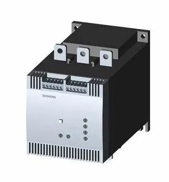
356 A at 40 °C — the thermal ceiling that governs the BOM line
The 3RW4075-6BB35: That 40 °C base is the derating temperature — above it the thyristor junction temperature rises faster than the heat sink can shed, so the continuous output current must be reduced per the manufacturer's curve. For a 300 A motor in a 45 °C panel, this part holds the unit on the grid with margin; for a 350 A motor at 50 °C, the 315 A ceiling means the starter will trip on overtemperature during a stalled-rotor start unless the ambient is brought down or a larger frame is selected.
Mounting and panel integration — S12 frame, screw-fixed, clearance zones
The S12 frame measures 160 mm wide by 230 mm tall by 278 mm deep, fastened to the backplate with screws — no DIN-rail snap-on. The mounting position is constrained by the fan: with the fan fitted, the unit can be rotated ±90° on a vertical surface and tilted ±22.5° front-to-back; without the fan, rotation is limited to ±10° and tilt to ±10°. These limits keep the thyristor heat sink within its designed convection path — exceeding them starves the cooling fins and derates the output below the published numbers. Clearance zones: 100 mm above the unit for cable bend radius and arc-flash standoff, 75 mm below for bottom-entry gland plates, and only 5 mm at the sides — tight side-by-side mounting is allowed, provided the top and bottom clearances are respected. The main power circuit accepts stranded cable 70 to 240 mm² or finely stranded 50 to 240 mm², with both front and back clamping points rated for 2/0 to 500 kcmil (North American sizes). For high-current feeds, busbar connection is also supported.
Thyristor switching and protection — no mechanical contacts, integrated overload
Switching is done by thyristors — semiconductor devices that turn on and off at the zero-crossing of the AC waveform, so there are no mechanical contacts to weld, pit, or arc. The minimum load is 20 % of the rated current; below that the motor current may not be sufficient to hold the thyristors in conduction, causing them to drop out and re-trigger on every half-cycle, which generates harmonics and heats the motor. For very light loads (pumps running dry, unloaded conveyors), a minimum-load resistor or a bypass contactor after start completion is standard practice. Motor overload protection is integrated — the soft starter measures motor current and trips on an I²t curve, so no separate overload relay is needed in the power circuit. Intrinsic device protection (thyristor over-temperature and over-current) is also built in, and an external reset input allows remote fault recovery from a DCS or PLC digital output. The adjustable current limitation lets the starting current be set between 20 % and 100 % of the motor full-load amps, which is the primary tool for tuning the start ramp to the load inertia. This is the standard industrial environment for motor control centres (MCCs) and panel shops; no additional conformal coating or sealed enclosure is required for normal factory-floor conditions.