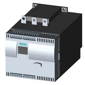
232 A at 40 °C — the continuous rating that defines the motor
The 3RW4435-6BC45: The derating temperature starts at 40 °C, meaning any enclosure that runs above that ambient must be sized for the lower current or forced-air cooled. The operating frequency is 50/60 Hz — no derating needed when switching between mains frequencies. Pollution degree 3 per IEC 60947-4-2 confirms this is built for industrial environments with conductive dust and humidity, not clean-room or light-commercial installs.
Thyristor switching and inside-delta wiring
Switching is done by thyristors — no mechanical contacts to wear, and the starting current profile is fully programmable. The unit supports inside-delta circuit connection, which reduces the current the soft starter sees to 58% of the line current — a 232 A unit in inside-delta can start a motor with 400 A line current. This is the standard wiring for larger soft starters where the line-side breaker and cabling are the cost driver. Motor overload protection is built in, so no separate overload relay is needed in most installations. The adjustable current limitation lets the user set the starting current peak below the upstream breaker's magnetic trip threshold — useful when the supply transformer is marginal or the line is shared with other loads. Minimum load is 8% — the soft starter can regulate down to very low current levels, which matters for unloaded motor starts or pump soft-stop where the load drops near zero before the stop ramp finishes.
Panel fit and termination — 270 mm depth, busbar connection
Dimensions are 270 mm deep, 170 mm wide, 200 mm tall. The 270 mm depth is the critical cabinet dimension — most 600 mm deep enclosures leave 330 mm for wiring and heat sink clearance behind the door. Main circuit termination is busbar connection, accepting stranded wire 25-120 mm², finely stranded 16-95 mm², and kcmil 4-250. The auxiliary contacts use 2x (20-14) AWG and the solid wire terminals are 2x (0.5-2.5 mm²). For North American installs, the busbar lugs accept 6-2/0 AWG at both front and back clamping points, and up to 2x 1/0 using both points. Clearance requirements: 100 mm above, 75 mm below, 5 mm at the sides. The 5 mm side gap is tight — adjacent units can be mounted nearly touching, but the top and bottom clearance must be respected for heat dissipation from the thyristor heat sink.
Active production — current lifecycle status
Sourced through independent distribution against an RFQ.