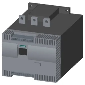
Panel fit and mounting — 298 × 210 × 230 mm
The 3RW4445-2BC45 occupies a 298 mm depth, 210 mm width, and 230 mm height envelope — a substantial footprint that requires a dedicated backpanel area in the cabinet. Mounting is by screw fixing, not DIN rail; the unit accepts a vertical mounting surface with ±90° rotation and ±22.5° tilt forward or backward, so the panel layout must account for the orientation range during installation. Clearance requirements: 100 mm above, 75 mm below, and only 5 mm at the sides — this tight side clearance means adjacent components can sit close, but the vertical airflow path needs the full 100/75 mm free space for convection cooling.
Current derating and thermal budget — 542 A at 40 °C baseline
The insulation voltage is rated 690 V, and the operating frequency covers 50 to 60 Hz, so the unit suits standard three-phase motor supplies across global line voltages up to 690 V. Derating temperature is specified at 40 °C — above this, the continuous current rating follows the published curve; the device also includes intrinsic device protection and motor overload protection, meaning no separate overload relay is needed for the motor branch.
Inside-delta circuit and adjustable current limitation
The 3RW4445-2BC45 supports inside-delta wiring, which reduces the current through the thyristors to 58 % of the line current — a key feature for large motors where the soft starter can be downsized relative to the motor FLA when wired in this configuration. Adjustable current limitation lets the commissioning engineer set the start current between 8 % and 100 % of the rated current — the 8 % minimum load capability means the starter handles light-load applications without dropping out. Thyristor-based switching (no contactor bypass built in) means the power semiconductors handle the full start and run current; an external bypass contactor can be added for continuous-duty efficiency, but the unit itself is rated for continuous thyristor conduction.
Termination and wiring — main circuit busbar, auxiliary screw clamps
Main current circuit connections use busbar terminals, accepting stranded wire from 70 to 240 mm² and finely stranded from 50 to 240 mm², or kcmil sizes from 2/0 to 500 kcmil using both clamping points. The front clamping point accepts 3/0 to 600 kcmil; the back clamping point accepts 250 to 500 kcmil — useful when paralleling cables for high-current runs. Auxiliary control wiring uses screw terminals accepting solid wire 0.25 to 1.5 mm² or stranded 24 to 16 AWG — standard for the 24 VDC control loop. Maximum motor cable length is 500 m — sufficient for most industrial installations; longer runs may require output reactors to limit reflected wave stress on the motor insulation.
Environmental and protection ratings
Operating temperature range during operation is up to 60 °C ambient; storage range is -25 to +80 °C — qualification engineers should note the storage limits for spares holding. The unit includes a display for fault signalling and supports external reset — useful for remote fault acknowledgement in automated lines.