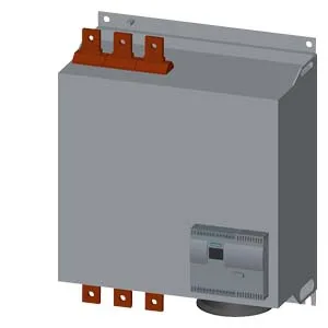
Current capacity across the ambient range
The 3RW4458-6BC46: That 40 °C figure is the ceiling for full current — above it the continuous rating drops linearly, so a panel that runs warm (50 °C+) needs to account for the 12 % reduction from the 40 °C nameplate. Pollution degree 3 per IEC 60947-4-2 means it lives in an industrial enclosure where conductive dust or occasional condensation is expected.
Integrated bypass and inside-delta wiring
An integrated bypass contact system closes after the start ramp, shunting the thyristors. During run the current flows through the bypass — the power section generates no heat, which keeps the enclosure cooler and eliminates the need to derate for continuous thyristor conduction. The bypass also extends the life of the thyristors since they only carry current during the start interval. Inside-delta circuit wiring is supported — this reduces the current through each thyristor to 58 % of the motor full-load current, allowing the starter to handle a larger motor than the line-current rating suggests. For a given motor FLA, inside-delta connection effectively increases the starter's capacity by about 1.73×.
Built-in protection and control features
Motor overload protection is onboard — no separate overload relay needed. The electronic overload tracks motor current and trips on a class 10 or class 20 curve, adjustable to match the motor's thermal damage curve. Intrinsic device protection monitors the thyristor junction temperature and shuts down before the power section is damaged. Adjustable current limitation lets you set the maximum starting current as a multiple of the motor FLA, typically 2 to 5 times. This protects the supply transformer and downstream cables from high inrush. Minimum load is 8 % — the starter can soft-start lightly loaded motors (conveyors, pumps running dry) without oscillation or unstable ramping. An integrated motor brake output controls a DC injection brake or mechanical brake coil directly, saving an external contactor. The onboard display shows fault codes — no need to carry a laptop to read the trip cause.
Mounting, wiring, and panel layout
Dimensions are 640 mm high, 510 mm wide, 290 mm deep — a large frame that needs a substantial panel backplate. Fastening is screw fixing (not DIN-rail), so the panel must have threaded mounting points or a mounting plate. The mounting position allows ±90° rotation and ±22.5° tilt from vertical, giving some flexibility in cabinet layout. Clearance requirements: 100 mm above, 75 mm below, only 5 mm at the sides. The tight side clearance is a space saver — units can be mounted side-by-side with minimal gap. The main circuit connects via busbar (not cable lugs), so the panel busbar system must be designed to match the terminal layout. Cable connections use stranded 70…240 mm² or finely stranded 50…240 mm², or 2/0…500 kcmil for the main contacts. Maximum motor cable length is 500 m — long cable runs from the starter to the motor are allowed without additional output filters.