Motor starting profile and overload coordination
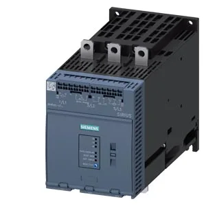
The 3RW5056-2TB14: Rated voltage 200-480 V and minimum settable current 81 A define the motor frame size this unit handles — match the FLA of the motor to the lower end of the adjustment range for proper protection. Trip Class 10A / 10E (preset) / 20E per IEC 60947-4-2 gives three overload protection profiles: Class 10A for standard starts, Class 10E for electronic overload matching, and Class 20E for high-inertia loads that need longer acceleration time before tripping. Minimum load of 15% relative to the smallest settable Ie means the soft starter can handle lightly loaded motors without nuisance tripping on undercurrent — useful for centrifugal pumps or fans that start unloaded.
ATEX and IECEx — what they mean for hazardous-area installations
ATEX and IECEx certification (both marked Yes) means this soft starter carries the paperwork for installation in explosive atmospheres per the ATEX directive 2014/34/EU and IECEx scheme — essential for oil & gas, chemical, or grain-handling lines where motor starting occurs in a classified zone. The unit still requires an upstream motor protection device (circuit breaker or fuses) coordinated with the soft starter's overload curve to maintain the Ex protection concept — the soft starter alone is not the sole protective device in the hazardous circuit.
Fieldbus integration — which networks it talks to natively
Native PROFIBUS DP, Modbus RTU, Modbus TCP, and EtherNet/IP support means this unit drops into most plant-floor networks without a separate gateway module — the commissioning engineer sets the node address and baud rate during startup. PROFIenergy function is available but requires the PROFINET standard communication module as a special accessory — budget for that if the site uses PROFINET and needs energy management data from the soft starter. Error logbook is present but only in conjunction with special accessories — the base unit does not store fault history onboard; plan for an external logging device if fault recording is needed for diagnostics.
No stock-holding claim — confirm lead time for your lot size before committing the production schedule. Regulatory approvals CE, UL, and CSA cover North American and European installations — no additional certification steps needed for most standard industrial panels shipping to these regions.
Panel layout and mounting clearances
Dimensions 249 mm depth, 120 mm width, 198 mm height — the width fits a standard 120 mm DIN-rail footprint, but note the depth requires 249 mm of enclosure depth clearance for the heat sink and wiring space behind the unit. Mounting position allows vertical surface mounting with ±90° rotation and ±22.5° tilt forward/backward — useful for tight enclosures or angled back panels, but derating above 40°C ambient must be observed per the operating temperature range of -25 to +60°C. Required clearances: 100 mm upwards, 10 mm forwards, 0 mm backwards, 75 mm downwards, 5 mm at the side — the zero backward clearance means the unit can sit flush against the back panel, but the 75 mm downward gap is mandatory for heat dissipation from the power section.