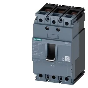
Its 3-pole construction and 20 A rating at 40 °C (derated to 19 A at 65 °C) make it a fit for moderate-load branch circuits where thermal-magnetic coordination is the standard. The 52.5 kA breaking capacity at 240 V AC gives substantial fault-current headroom for most commercial and light industrial panels; at 415 V it still interrupts 32 kA, enough for European 400 V distribution where the prospective fault current rarely exceeds 25 kA.
The 20 A continuous rating holds flat from 40 °C to 55 °C; above that it derates to 19 A at 70 °C. In a sealed, non-ventilated enclosure at 60 °C ambient, the breaker still carries 19 A continuous without nuisance tripping. Breaking capacity varies with system voltage: 52.5 kA at 240 V, 32 kA at 415 V, 13.6 kA at 440 V, and 7.5 kA at 500 V and 690 V. The 7.5 kA at 690 V is the limiting case — if your transformer secondary can deliver more than 7.5 kA at 690 V, this breaker will not clear a bolted fault. That is the number to check first when specifying for a 690 V drive panel. The 12 W maximum power loss is the heat the breaker dumps into the enclosure at full rated current. In a multi-breaker lineup, sum these losses and check the enclosure's dissipation rating — a 12-breaker panel running at 20 A each sheds 144 W internally, which can raise the internal ambient above the 55 °C flat-rating ceiling.
The auxiliary switch configuration is factory-fitted as 4 HQ auxiliary switches — these are built into the breaker housing, not field-added. If your control scheme requires more than four auxiliary contacts or a different contact arrangement (e.g., early-make / late-break for signaling), factor that into the order code selection rather than planning a field modification.
Physical integration
The breaker measures 130 mm high, 76.2 mm wide, and 70 mm deep — a standard 3-pole MCCB footprint that fits most Siemens SENTRON distribution panels and third-party enclosures with a 70 mm depth allowance. The 76.2 mm (3-inch) width is the critical dimension for multi-pole ganging in a panelboard; verify the busbar spacing matches before committing the layout. If the application requires any of those — for emergency-stop undervoltage protection, remote tripping, or earth-leakage detection — a different order code within the 3VA10 family is needed. The basic switch base (3VA10202ED320AA0) is the core mechanism; this code adds the TM210 release and the 4-HQ auxiliary switch block.