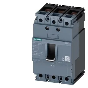
Siemens SENTRON 3VA1032-4ED32-0KH0 — 32 A MCCB with TM210 Release
It carries a TM210 thermal-magnetic overcurrent release — the '210' designator indicates the thermal pickup is fixed at 1.0× Iu (32 A) and the magnetic short-circuit pickup is fixed at 10× Iu (320 A), per the TM210 designation. Breaking capacity is rated per IEC 60947-2 at multiple voltages: 121 kA at 240 V AC, 75.6 kA at 415 V AC, 52.5 kA at 440 V AC, and 11.9 kA at 690 V AC. These are the Icu (ultimate short-circuit breaking capacity) values — the breaker can interrupt one fault at these levels and remain functional, though not necessarily fit for further service without inspection. For a panel builder, the 75.6 kA at 415 V covers most European industrial distribution boards; the 52.5 kA at 440 V is relevant for 480 V North American systems where the line-to-line voltage sits near that level. Current-carrying capacity is rated at 32 A from 40 °C through 50 °C ambient, then derates linearly: 30.72 A at 55 °C, 30.08 A at 60 °C, 29.44 A at 65 °C, and 28.8 A at 70 °C.
Dimensions: 130 mm height, 76.2 mm width (3-pole), 70 mm depth. The 76.2 mm width is standard for a 3-pole MCCB in this frame size — it occupies three 25.4 mm (1-inch) pole spaces on a DIN rail or panel-mount footprint. The breaker includes a trip indicator (mechanical flag) and a voltage trigger — these are visual and electrical status signals for troubleshooting. The shunt trip release (STL) is integrated; its order code is 3VA9688-0BL33. The base switch variant is 3VA10324ED320AA0 — useful for ordering replacement internals if the breaker is damaged but the enclosure and terminals are intact.
If a panel was specified around a different 3VA variant (e.g., 3VA1010-2ED32-0JC0 or 3VA1020-3ED36-0AA0), the physical footprint and mounting pattern are the same across the 3VA frame — the difference is in the release type, auxiliary contact count, and rated current. The 3VA1032-4ED32-0KH0 will drop into the same panel cutout and DIN rail position as those siblings, but the wiring for the shunt trip and auxiliary contacts must be verified against the original schematic.