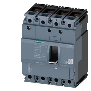
No undervoltage release, no ground fault monitoring, no communication function, and no phase failure detection are fitted. Breaking capacity is rated at 75.6 kA at 240 V, 52.5 kA at 415 V, 32 kA at 440 V, and 7.5 kA at 690 V. At 40 °C through 50 °C it carries the full 50 A; derating begins at 55 °C (48 A), dropping to 45 A at 70 °C. Dimensions: 130 mm height, 101.6 mm width, 70 mm depth. Latching endurance rated at 15 000 cycles.
The TM210 release means trip settings are factory-fixed; no field-adjustable thermal or magnetic dials. If your BOM calls for electronic adjustability or zone-selective interlocking, this is not the variant. At 690 V the capacity drops to 7.5 kA — verify available fault current if this breaker lands on a 690 V bus. The 75.6 kA at 240 V covers high-fault North American 240/120 V services. The 4-pole design with neutral protection absent (no N-conductor protection) means the fourth pole is a switched neutral, not a protected pole. If your application requires neutral protection, this unit does not provide it.
The 101.6 mm width (4-pole) occupies four 25 mm module spaces — plan gland-plate fill accordingly. The two HQ auxiliary switches are wired separately; verify the free-wheeling diode polarity on the shunt trip coil (STL) before energizing. No communication module or voltage trigger tap is present — this is a standalone breaker, not a power-monitoring node.