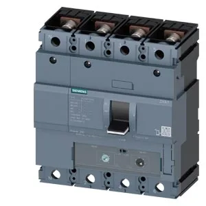
That 250 A holds flat from 40 °C through 50 °C (–), then derates to 243.3 A at 55 °C, 236.5 A at 60 °C, 229 A at 65 °C, and 223 A at 70 °C (–). Breaking capacity is the headline: 121 kA at 240 V, 75.6 kA at 415 V, 25 kA at 440 V, and 11.9 kA at 690 V. The 121 kA figure at 240 V means this breaker handles high-fault utility feeds or transformer secondaries without cascading upstream — common in North American 240 V delta or 277/480 V wye services where the available fault current at the panelboard exceeds 100 kA. At 415 V (typical IEC industrial), 75.6 kA covers most main and feeder applications. The 690 V rating at 11.9 kA is lower; verify SCCR if the line side is a 690 V transformer. Mount inside a panel with at least an IP54 enclosure if the environment is dirty or wet.
Auxiliary and trip configuration
The trip alarm switch (HQ) changes state only when the breaker trips on fault, giving a discrete signal distinct from the auxiliary position. This is a straight line-protection MCCB — thermal-magnetic only, no electronics, no metering. If you need ground-fault or phase-loss protection, it must be added externally.
Dimensions: 140 mm wide, 158 mm high, 70 mm deep. The 140 mm width is standard for a 4-pole 250 A frame in the 3VA series — it occupies three 45 mm-wide modular positions plus one. The 70 mm depth includes the rear terminals; allow clearance for cable bending and the shunt trip wiring. Mounts via screw-clamp to a backplate or DIN-rail adapter (Siemens mounting kit). Latching endurance rated at 15 000 operations — mechanical life, not electrical. For frequent switching duty (motor starting or capacitor bank), consider a contactor instead; this MCCB is designed for infrequent isolation and fault protection.