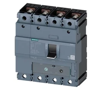
That 250 A is the thermal continuous rating — the breaker will carry that current indefinitely at 40 °C without tripping. At 55 °C it derates to 243.3 A, and at 70 °C to 223 A, so if the panel ambient runs hot, the actual load must be reduced accordingly. The breaking capacity tells you the maximum fault current the breaker can safely interrupt at a given voltage: 220 kA at 240 V, 154 kA at 415 V, 36 kA at 440 V, and 17 kA at 690 V. On a 415 V distribution board with a prospective fault current of, say, 100 kA, this breaker has headroom. The breaker's rated continuous current is 250 A, so the TM240 release sets the trip threshold below the frame rating. This is a common configuration for line protection where the cable or bus is sized for 250 A but the protection needs to coordinate at 240 A.
Four-pole MCCBs at this frame size typically mount on a DIN rail or bolt directly to a mounting plate. The 140 mm width is the critical dimension for multi-breaker lineup spacing — verify your enclosure's backplate layout allows that pitch per pole. No auxiliary contacts are fitted as standard; the auxiliary release is a shunt trip (STL) with the integrated auxiliary trip specified as 3VA9688-0BL30. If you need a separate auxiliary contact block, it must be ordered and installed separately.