At 415 V and 440 V the interrupting rating holds at 121 kA; at 500 V it drops to 75.6 kA, and at 690 V to 52.5 kA. That derating curve is typical for MCCBs — the arc extinction gets harder as voltage rises. For a 480 V panel (common in North America) the relevant figure is the 500 V column at 75.6 kA, which still covers most utility transformer fault levels.
Panel integration — dimensions, auxiliaries, and thermal management
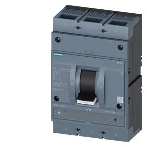
It ships with a factory-fitted auxiliary switch configuration: 1 auxiliary switch + 1 trip alarm switch HQ. That covers remote status and trip indication without a separate accessory order. The undervoltage release is absent by default, so if your safety circuit requires a shunt trip or UVR, you will need to add the appropriate module. Maximum power loss is 240 W at rated load; at 800 A continuous, that heat must be managed in the enclosure — plan for forced ventilation or a larger-than-minimum cabinet volume to stay below the 70 °C operating maximum.
Selectivity and coordination — where this fits in a distribution hierarchy
As a line-protection MCCB, this breaker is designed for the main or sub-feed position, not for branch-circuit motor protection. The TM240 release provides a fixed thermal curve that coordinates with downstream SENTRON 3VA or 5SY miniature breakers, provided the fault current stays within the 187 kA interrupting rating. For a 800 A main feeding 200 A or 400 A feeders, the selectivity margin is generous — the TM240 magnetic pickup is typically 10× In, so instantaneous trips start above 8000 A, giving downstream breakers time to clear. If you need ground-fault protection, note this variant ships without ground-fault monitoring; order the GF version or add an external ground-fault relay.