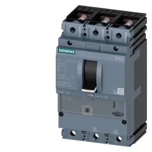
What it is and what the ratings mean for fit
The Siemens SENTRON 3VA2110-7MS32-0AG0 is a 3-pole molded case circuit breaker (MCCB) in the starter protection version, meaning it's designed for motor branch-circuit protection — it combines short-circuit and overload protection in one device sized for motor starting duty rather than straight feeder protection. The rated continuous current Iu is 100 A, which sets the maximum continuous load the breaker can carry without tripping under normal conditions; for a motor branch, this typically matches the full-load current of the driven motor plus the NEC 430.32 sizing margin. The breaking capacity tells you the maximum fault current the breaker can safely interrupt at a given voltage: 330 kA at 240 V, 242 kA at 415 V and 440 V, 187 kA at 500 V, and 52.5 kA at 690 V. These are very high values — the 330 kA at 240 V is well into the current-limiting range, which means on a high-fault panel (like a transformer secondary or a large motor control center) this breaker can clear a bolted fault without the arc flash energy escalating. The rated insulation voltage Ui is 800 V, confirming the breaker's internal insulation system is rated for 800 V phase-to-phase, so it's suitable for 480/277 V and 600/347 V North American systems as well as 400 V and 690 V IEC systems.
Thermal derating and the real-world current limit
The 100 A rating holds flat from 40 °C through 50 °C ambient — no derating needed in a typical 40 °C panel. At 55 °C it drops to 96 A, at 60 °C to 94 A, at 65 °C to 92 A, and at 70 °C to 90 A. If the breaker is mounted in a hot enclosure (near a drive, transformer, or in a non-ventilated cabinet), use the 90 A figure at 70 °C as your continuous load limit. The maximum power loss is 75 W at rated current; that's the heat the breaker dumps into the enclosure, so factor it into the panel thermal calculation. Operating temperature range is -25 °C to 70 °C; storage range is -40 °C to 80 °C.
Release, aux contacts, and integration notes
The overcurrent release is the ETU310M, an electronic trip unit with LSI curves (long-time, short-time, instantaneous) — adjustable, so you can coordinate selectively with downstream breakers. The auxiliary contact configuration is 1 auxiliary switch + 1 trip alarm switch HP, which gives you one N.O./N.C. set for status feedback (breaker open/closed) and one dedicated to signaling a trip event. There is no undervoltage release, no shunt trip, no ground-fault monitoring, and no communication module on this variant. Physical dimensions: 105 mm wide, 181 mm tall, 86 mm deep. That 105 mm width is the standard 3-pole MCCB footprint for this frame size; it mounts on a DIN rail or panel-mount baseplate in a standard distribution panel.
