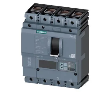
That 160 A holds at every 5 °C increment, per the datasheet, so you can size the bus and downstream conductors to a flat 160 A without calculating temperature correction factors for the breaker itself. This is a line-protection design (not motor or generator protection), so the trip characteristics are optimized for feeder and distribution panels where selectivity with downstream breakers matters. The communication function allows integration with a BMS or SCADA for remote trip indication and power monitoring — useful for a plant engineer tracking fault events without walking the panel. Breaking capacity is specified per voltage: 440 kA at 240 V, 330 kA at 415 V and 440 V, 220 kA at 500 V, and 52.5 kA at 690 V. At 415 V — common for industrial distribution in many regions — the 330 kA rating covers virtually any fault level you will encounter on a secondary substation bus. The 690 V figure of 52.5 kA is still substantial for a 160 A frame; it handles high-impedance faults on 690 V mining or marine systems without cascading upstream.
This part carries a lifecycle status of current, meaning Siemens continues to manufacture it as an active catalog item. For a procurement or MRO planner, that means the BOM line is stable — no need to qualify a substitute or stockpile for obsolescence.
Dimensions: 86 mm depth, 140 mm width, 181 mm height. Mounting is via the standard 3VA base plate or DIN rail adapter (not included). Panel builders should verify the terminal spread against the busbar drilling pattern — the 4-pole layout at 140 mm width is a common footprint, so it drops into most distribution boards without re-drilling.