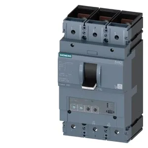
Its interrupting capacity scales from 121 kA at 240 V down to 7.5 kA at 690 V — the voltage-dependent SCCR curve is the real coordination spec for the fault-current study, not a single number.
Continuous current holds at 400 A from 40 °C through 50 °C, then derates linearly to 340 A at 70 °C. That flat thermal curve means no headroom loss in a warm panel until you cross 55 °C — common in enclosed switchgear near process heat. The 400 A full-scale value is the BOM line item; the 80 A initial setting (likely the adjustable thermal pickup floor) gives range for motor or feeder circuits that don't need the full frame. Interrupting capacity: 121 kA at 240 V, 75.6 kA at 415/440 V, 52.5 kA at 500 V, 7.5 kA at 690 V. The ground-fault monitoring uses summation current formation on the L-conductor, not a separate GFCI module; that's built into the trip unit for this variant.
Panel integration and physical fit
Dimensions: 110 mm deep, 138 mm wide, 248 mm tall. The 138 mm width on a 3-pole frame fits a typical DIN-rail enclosure section with room for side-mounted auxiliaries.