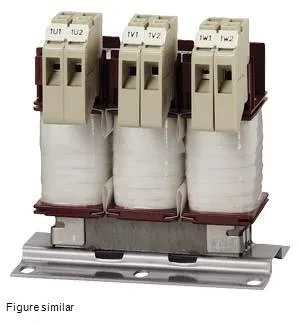
The 0.3mH inductance limits the rate of current rise from the drive's PWM output, which reduces motor cable reflections and bearing currents on long cable runs. The 8kHz switching frequency matches the typical IGBT carrier frequency of modern VFDs — if your drive runs at a different carrier, the reactor still works but derates the current; the 14A figure is the thermal limit at the rated 8kHz and 55°C ambient. The screw-type terminals accept field wiring directly; no lugs or ring terminals are required, but the connection point is live when the panel is energized. Thermal class B insulation (130°C hot-spot) per IEC 60085, with combined copper and iron losses of 62W at rated load. That heat has to be managed inside the enclosure — plan for natural convection or forced airflow around the reactor.
Mounts in the motor cable path between the VFD output and the motor terminals. The 0.12m depth, 0.17m width, and 0.15m height footprint fits a standard DIN-rail backplate or panel floor; the screw terminals accept conductors sized for the 14A circuit. Because it's IP00, it must be inside a panel with at least IP2X protection on the enclosure door. The 167Hz minimum operating frequency means it's designed for PWM carrier frequencies, not line-frequency (50/60 Hz) chokes. It will saturate at line frequency — don't use it as a line reactor.