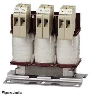
Its job is to limit the rate of rise of current (di/dt) during commutation events in the rectifier — reducing harmonic distortion, protecting the DC-link capacitors, and smoothing the current waveform so the drive or inverter sees a cleaner supply. Rated for 40.5 A continuous at 500 V AC, 50 Hz, with a peak current capability of 56 A and a DC rated value of 55.1 A, this choke sits between the supply and the converter input. The 0.65 mH inductance and 4% relative inductive voltage drop are the key numbers that determine its filtering effect; the 4% drop means it's sized for moderate harmonic mitigation — enough for most variable-speed drive installations without excessive voltage loss under load.
Thermal and mounting reality
This is an IP00 choke — no enclosure, no finger protection. The thermal class B insulation (130 °C continuous) and 70 W coil loss plus 16.5 W iron core loss mean it dissipates about 86.5 W total at rated load. In a panel, that heat has to be managed: the 0.219 m width, 0.179 m height, and 0.123 m depth dimensions give it a moderate footprint, but the 40 °C ambient temperature rating means derating is required above that — a panel at 50 °C ambient will need to reduce the continuous current or add forced ventilation.
The headline numbers that govern fit are the 40.5 A rated current (AC, 3-phase, 50 Hz) and the 500 V operating voltage. The 56 A peak current tells you the choke can handle short-duration overloads — typical for motor starting or converter inrush — without saturating. The DC rated value of 55.1 A is relevant if the choke is used on the DC link side of a converter, though the primary application is AC line-side. The 4% voltage drop at rated current and frequency is the impedance figure: a 4% choke is a common choice for general-purpose drive input filtering. Too low (1-2%) and you get less harmonic attenuation; too high (5-8%) and you start losing significant voltage to the choke, which can reduce motor torque at the end of a long cable run. This 4% value is a balanced middle ground. The 0.65 mH inductance per phase is the actual design parameter that determines the resonant frequency of the L-C filter formed with the DC-link capacitors; if you're replacing a choke in an existing drive cabinet, match this inductance value within ±10% to avoid shifting the filter's cutoff frequency.