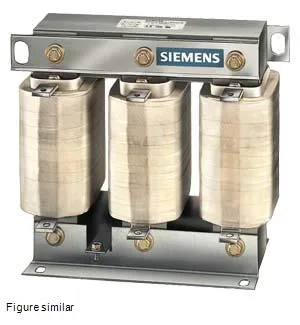
Commutating choke for converter duty
It limits current rise and harmonics on the AC side of a variable-frequency drive or DC drive supply. Rated 500 V AC, 50 Hz, with a maximum continuous AC current of 63 A and a DC-rated current of 77.2 A — the DC figure matters if you're using it in a six-pulse rectifier output where the DC link sees the higher average current. That 4% drop is typical for a line reactor sized to keep harmonics within IEEE 519 guidelines without dropping too much voltage across the choke under load.
Three current figures are listed, and each governs a different operating condition. The 63 A AC maximum (Ithmax) is the thermal continuous rating at 50 Hz — this is the number you compare to the drive input current. The 56.7 A AC operational current (ILN) is the rated continuous current under the specified inductive drop. The 77.2 A DC rating reflects the current the choke can carry when installed on the DC side of a converter. If you're placing it on the AC line, size for the 63 A figure; if on the DC bus, the 77.2 A limit applies. Power loss splits into 80 W in the coil and 25 W in the iron core — 105 W total at rated load, which means forced convection or spacing from heat-sensitive components in a closed panel. Thermal class B (130 °C) insulation according to IEC 60085 gives the hot-spot limit.
IP00 — no enclosure, no drip shield. Dimensions are 0.219 m wide, 0.179 m high, 0.143 m deep. The main circuit connects via flat-type terminals (bus-bar or crimp-lug compatible). No DIN-rail clip; expect bolt-down mounting through the core or baseplate. Ambient temperature rating is 40 °C; derate above that per the thermal curve.