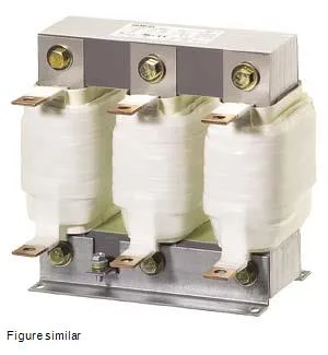
The Siemens SIDAC 4EU2431-0UA00-0A is a 3-phase output reactor (also called an output choke) designed to sit between a variable-frequency drive and the motor. Its job is to limit the rate of voltage rise (dV/dt) and reduce reflected-wave peaks on long cable runs, protecting the motor winding insulation from premature failure. The reactor is rated for a maximum continuous current of 47 A and a fundamental frequency range of 0 to 120 Hz, with a rated switching frequency of 3 kHz.
The 47 A maximum current sets the upper limit for the motor full-load amps this reactor can handle continuously. The operational current at AC rated value is 42.3 A, which is the design-point current under nominal conditions — a useful figure for sizing against a specific motor nameplate. The 0.18 mH inductance and 2.4% impedance define the choke's filtering effect; a lower inductance gives less suppression but also less voltage drop at the motor terminals. The 3 kHz switching frequency matches the carrier frequency of most modern PWM drives — if your drive runs a higher carrier (8–16 kHz), this reactor still works but the filtering effectiveness shifts; the datasheet's impedance curve (not reproduced here) would show the actual attenuation at your operating frequency. The flat-type terminals accept busbar or lug connections, not spring-cage or screw-clamp wire terminations. Plan for a panel-mounted connection point and adequate clearance around the core for airflow. The thermal class H insulation per IEC 60085 means the winding can tolerate a 180 °C hot-spot temperature, which is standard for reactor duty where the core and copper losses generate significant heat. Power loss is split between the coil (110 W) and the iron core (81.9 W), totaling roughly 192 W at rated load. That heat must be removed from the enclosure — factor it into your panel thermal budget. The ambient temperature rating of 40 °C is the maximum surrounding air temperature for full-load operation; derate current above that per the manufacturer's curve.
Output reactors of this class are deployed in motor drive circuits where the cable run between the drive and motor exceeds about 30 meters (or 10 meters for 690 V drives). They are standard in conveyor systems, pump stations, fan arrays, and any variable-speed application where reflected-wave damage is a risk. The 460 V line-to-line voltage places it in the 400–480 V class common across North American and European industrial installations.