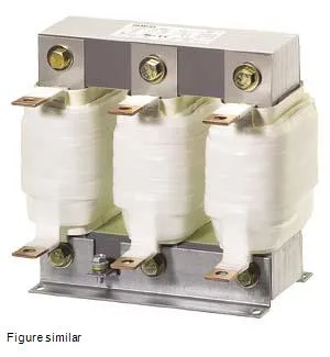
What this mains choke does for a drive line
It sits between the supply and the drive, limiting harmonic currents and reducing the rate of voltage rise (dV/dt) that can stress the drive's rectifier and DC bus. Rated 319.5 A continuous with a 355 A maximum, it handles the full load current of a large drive — think pumps, conveyors, or compressors in the 200+ kW range on a 400 V or 480 V three-phase line. That 4% figure is typical for line reactors sized to meet IEEE 519 harmonic limits without over-dropping voltage and starving the drive. At 400 V, expect roughly 16 V dropped across the choke at 319.5 A — the drive compensates internally, but the motor's available torque at the shaft drops proportionally. If your drive is already marginal on voltage, a 2% choke might be a better fit. This is an open-frame (IP00) component — no enclosure, no finger-safe covers. It mounts inside a panel or cabinet where the live flat-type terminals are protected by the enclosure's own IP rating. The 0.221 m depth by 0.3 m width by 0.269 m height footprint needs a generous backplate; plan for at least 50 mm clearance around the choke for airflow, because the combined coil and iron losses total 345 W (216 W coil + 129 W iron) at full load. That heat has to leave the cabinet — factor it into your ventilation or forced-air cooling budget.
UL and CSA recognition is confirmed, so the choke carries the approvals needed for North American panel builds. The thermal class H insulation means the winding can handle a 180 °C hot-spot temperature — well above the 40 °C ambient rating, giving a solid thermal margin even in a warm cabinet.
Integration notes — what fits, what doesn't
The main circuit connects via flat-type terminals. These are bus-bar style lugs, not screw-clamp or ring terminals — expect to bolt on a copper bar or a crimped flat connector. Verify your drive's input cable lug matches the terminal width before ordering; the evidence does not specify the hole size or stud thread, so check the nameplate drawing if you're adapting existing cables. The 79 µH inductance is the actual line-reactor value that determines the current-limiting and harmonic-filtering performance. At 50 Hz, that gives roughly 0.025 Ω inductive reactance per phase; at 60 Hz, about 0.030 Ω. The 4% voltage drop figure is measured at rated current and frequency — if you run the drive at a lower load, the voltage drop scales linearly, and the harmonic attenuation improves. If you need to calculate the short-circuit current limiting, use the 79 µH value with your system's available fault current.