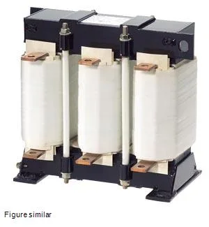
What this 3-phase output reactor does
The SIDAC 4EU3652-0AK00-1BA0 is a 3-phase AC output reactor (choke) rated for a maximum continuous current of 94A and a switching frequency of 8kHz, with an inductance of 0.15mH. It's designed to sit between a variable-frequency drive and the motor, smoothing the PWM waveform and limiting the rate of voltage rise (dV/dt) to protect motor winding insulation.
The 94A maximum current is the thermal limit under continuous duty at the rated 40°C ambient. For motor applications, this typically covers a drive rated around 75–90 kW on 400 VAC, but confirm the drive's output current against the reactor's continuous rating — the reactor must not be the bottleneck. The 8kHz switching frequency matches modern IGBT drives; if your drive runs a lower carrier frequency (2–4 kHz), the reactor still works, but core losses shift. The 0.15mH inductance provides enough impedance to limit motor terminal overvoltage on longer cable runs (up to about 100m, depending on cable capacitance). Power loss splits into 387W in the coil (copper losses) and 214W in the iron core (hysteresis and eddy-current losses), totaling roughly 600W at full load. That heat must be vented — in a sealed IP54 cabinet, factor this into the thermal budget or add forced air. The thermal class H insulation (180°C hot-spot) gives headroom for overloads, but the 40°C ambient limit is the design point; derate current above that. Termination is via flat-type connectors (busbar-style), not ring lugs or screw clamps. The panel builder needs to plan for bolted flat connections on the main circuit — not a terminal block. Dimensions are 0.35m wide, 0.32m high, and 0.22m deep, so it occupies a significant footprint on the backplate; check clearances for the flat connectors and bending radius of incoming cables.