What this output reactor does in the drive line
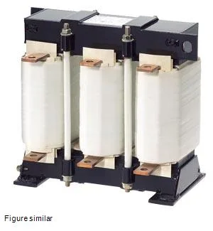
The Siemens SIDAC 4EU3652-0AP02-4BA0 is a 3-phase output reactor rated for 117 A maximum continuous current at 400 V AC, with a rated switching frequency of 8000 Hz. It sits between the VFD output and the motor cable to limit the rate of voltage rise (dV/dt) and reduce reflected-wave peaks on long cable runs — a common cause of motor winding insulation stress in PWM drives. The 0.1 mH inductance (0.0001 H) and 38.4 % impedance (UK) are sized to match the drive's carrier frequency and cable length, not the motor full-load amps alone. Total power loss at rated load splits between the coil (223 W) and the iron core (177 W), giving 400 W of heat to vent from the enclosure. Thermal class H (180 °C winding rise per IEC 60085) means the reactor can run hot without degrading the magnet wire insulation — important when the panel ambient hits 40 °C and the reactor is mounted near other heat sources. The flat-type main-circuit terminals accept busbar or cable lugs; plan for a 0.35 m width and 0.32 m height footprint on the backplate, with 0.22 m depth clearance for the winding overhang.
Mount the reactor on the backplate inside a ventilated cabinet — IP00 means no touch protection, so the live flat terminals must be shielded by the panel door or a separate guard. The 0.35 m width and 0.32 m height fit a standard 600 mm wide enclosure with room for cable entry below. Flat-type terminals suit busbar connection from the drive output; torque values follow the lug manufacturer's spec for the cable cross-section used. The 8000 Hz rated frequency matches most IGBT-based VFDs running a standard 4 kHz to 8 kHz carrier. If the drive is set to a higher carrier (12 kHz or 16 kHz), derate the reactor's current or verify with the drive manufacturer — the core losses scale with frequency.