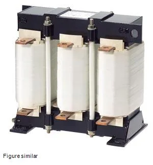
What this output reactor does on the drive output
Its 0.3 mH inductance and 8 kHz switching frequency rating mean it is designed to sit between a variable-frequency drive and the motor, smoothing the PWM voltage spikes that would otherwise degrade motor winding insulation over time. The 8 kHz figure matches the typical carrier frequency of many general-purpose drives, so this reactor will fit a standard VFD output without derating the switching stage. Rated power loss splits into 500 W in the coil and 300 W in the iron core, totalling 800 W at full load. That heat must be managed: the IP00 enclosure (open frame) requires the panel builder to provide forced-air cooling or enough free-air volume to keep the ambient below the 40 °C rating. Thermal class H per IEC 60085 means the insulation system handles 180 °C hot-spot, which gives margin above the 40 °C ambient if airflow is adequate.
Fit and integration — what the dimensions mean for the panel
At 0.41 m wide, 0.38 m high, and 0.22 m deep, this reactor occupies a floor footprint of about 0.16 m² and stands about the height of a standard 16-module DIN-rail enclosure. The flat-type terminals accept busbar or cable lug connections typical of 110 A power circuits; plan for M8 or M10 ring lugs depending on your local code.