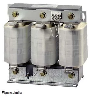
The Siemens 4EU4351-0EB10-0A is a 3-phase mains choke (Netzdrossel f. FU) designed for the input side of a frequency converter drive. Its job is to limit harmonic distortion, smooth line-side current, and provide a degree of protection against voltage transients upstream of the drive's DC bus. For a 1440 A drive input, this choke will drop about 9.2 V line-to-line at 50 Hz — a figure to verify against the drive's undervoltage tolerance, especially on weak grids. Mounting dimensions are 0.46 m wide by 0.435 m tall by 0.265 m deep — verify the available backplate or floor space before committing the BOM line.
The 1600 A maximum current and 1440 A rated current define the thermal and magnetic headroom. The rated current of 1440 A is the continuous RMS value the choke can carry at 40 °C ambient without exceeding its Class H (180 °C) insulation temperature limit. The 1600 A figure is the maximum permissible under the datasheet's conditions — likely the short-time thermal withstand or the absolute peak for a defined duty cycle. For a continuous 1440 A drive load, the choke is correctly sized; for a drive rated above 1440 A continuous, the choke would be the bottleneck. The 2 % voltage drop at rated current is the impedance-based regulation. On a 460 V line, that is roughly 9.2 V per phase at 50 Hz. If the drive's input voltage tolerance is ±10 % (414 to 506 V), the 9.2 V drop is well within margin. But on a 400 V nominal system running near the low end, the additional drop could push the drive into undervoltage alarm — check the drive's minimum operating voltage. The thermal class H (180 °C) insulation system means the choke can operate at elevated internal temperatures without accelerated aging. This is typical for high-current line reactors where copper losses generate significant heat. The 40 °C ambient rating is the reference point; derate the continuous current if the cabinet ambient exceeds 40 °C.
The main current circuit terminates on flat-type connectors — bus-bar or heavy-gauge cable lugs, not spring-clamp or screw terminals. The 0.46 m width and 0.435 m height mean it occupies a substantial footprint on the backplate or cabinet floor. Allow clearance around the flat connectors for tool access and bending radius of the incoming cables.