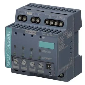
The 6AG1961-2BA31-7AA0 is a controlled DC voltage distribution module from the Siemens SITOP series—not a bulk power supply, but a four-output block that takes a 24V DC feed (22...30 V per the spec) and distributes it to four individually protected outputs. Each output has a non-accessible 5 A fuse and an adjustable current limit set via potentiometer. Overcurrent conditions trigger a fast switch-off (1.5x set value, typ. 100 ms) or a delayed switch-off (between 1.0 and 1.5x set value, approx. 5 s), giving you selectivity between short-circuit and moderate overload. Outputs are not parallelable. On power-up, the module delays output connection for 25 ms, 100 ms, or a load-optimised sequence selected via DIP switch—useful when charging downstream capacitive loads. Three-color LEDs per output indicate normal pass-through (green), manual off (yellow), or overcurrent trip (red). An optional non-isolated 24 V remote reset input (sensing >15 V as high) can clear a fault per output. The unit is rated for 97 % efficiency at nominal load. Mounts on DIN rail EN 60715 35×7.5/15. Screw terminals on input accept 0.5...16 mm²; output and signal terminals accept 0.5...4 mm². Enclosure dimensions 72 mm wide, 80 mm high, 72 mm deep; requires 180 mm of vertical clearance for terminal access. Protection class IP20, safety according to EN 60950-1 and EN 50178, emissions per EN 55022 Class B, immunity per EN 61000-6-2.
Siemens 6AG1961-2BA31-7AA0 Power Distribution Module, 4 Outp
MPN6AG1961-2BA31-7AA0
Siemens SITOP, power distribution module, 6AG1961-2BA31-7AA0, 24V DC input, 4 outputs, 97% efficiency, screw terminals, DIN rail mount, IP20.
StockContact for availability
MOQ1 pcs
Sourced new & surplus through independent channelsListing updated Jun 2026
Specifications
| Parameter | Value |
|---|---|
| Type of outputs connection | Simultaneous connection of all outputs after power up of the supply voltage > 20 V, delay time of 25 ms, 100 ms or adjustable "load optimised" via DIP switch for sequential connection |
| Fuse protection type at input | 5 A per output (not accessible) |
| Type of electrical connection | screw-type terminals |
| Type of response value setting | via potentiometer |
| Type of the power supply network | Controlled DC voltage |
| Type of test of the coating acc. to MIL-I-46058C | Yes; Discoloration of the coating during service life possible |
| Input voltage at DC | 22 ... 30 V |
| Voltage curve at output | controlled DC voltage |
| Formula for output voltage | Vin - approx. 0.2 V |
| Supply voltage at DC rated value | 24 V |
| Relative overall tolerance of the voltage note | In accordance with the supplying input voltage |
| Input current at rated input voltage 24 v rated value | 12 A |
All specifications+40 ▾
| Parameter | Value |
|---|---|
| Power loss [W] at rated output voltage for rated value of the output current typical | 9 W |
| Of the excess current | Iout = 1.0 ...1.5 x set value, switch-off after approx. 5 s |
| Of the current limitation | Iout = 1.5 x set value, switch-off after typ. 100 ms |
| Residual current at Switch-Off typical | 1 mA |
| Output current up to 60 °C per output rated value | 3 A |
| Adjustable current response value current of the Current-Dependent overload release | 0.5 ... 3 A |
| I/O channels | 4 |
| Depth of the enclosure | 72 mm |
| Width of the enclosure | 72 mm |
| Height of the enclosure | 80 mm |
| Mounting height | 180 mm |
| Installation width | 72 mm |
| In horizontal mounting position during operation | -25 ... +70 °C; with natural convection |
| Installation altitude at height above sea level maximum | 6 000 m |
| Ambient condition relating to ambient temperature - air pressure - installation altitude | In case of operation at altitudes of 2000 - 6000 m above sea level: Output power derating of -7.5 %/1000 m or reduction of the ambient temperature by 5 K/1000 m |
| CE marking | Yes |
| Standard for safety | according to EN 60950-1 and EN 50178 |
| At input | +24 V: 2 screw terminals for 0.5 ... 16 mm²; 0 V: 2 screw terminals for 0.5 ... 4 mm² |
| At output | Output 1 ... 4: 1 screw terminal each for 0.5 ... 4 mm² |
| Mounting | Snaps onto DIN rail EN 60715 35x7.5/15 |
| Other information | Specifications at rated input voltage and ambient temperature +25 °C (unless otherwise specified) |
| Protection class IP | IP20 |
| Efficiency in percent | 97 % |
| For signaling contact | 1 screw terminal for 0.5 ... 4 mm² |
| Remote reset function | Non-electrically isolated 24 V input (signal level "high" at > 15 V) |
| For auxiliary contacts | Remote reset: 1 screw terminal for 0.5 ... 4 mm² |
| Mechanical accessories | Device identification label 20 mm × 7 mm, TI-grey 3RT2900-1SB20 |
| For emitted interference | EN 55022 Class B |
| For interference immunity | EN 61000-6-2 |
| Of the immediate Switch-Off | Iout > set value and Vin < 20 V, switch-off after approx. 0.5 ms |
| During storage and transport | -40 ... +85 °C |
| Overvoltage overload capability | 35 V |
| Operating resource protection class | Class III |
| Display version for normal operation | Three-color LED per output: green LED for "Output switched through"; yellow LED for "Output switched off manually"; red LED for "Output switched off due to overcurrent" |
| Product feature parallel switching of outputs | No |
| Design of the reset device (Resetting mechanism) | via sensor per output |
| Design of the switching contact for signaling function | Status signal output (pulse/pause signal, can be evaluated via Simatic function block) |
| Galvanic isolation between input and output at Switch-Off | No |
| Chemical resistance to commercially available cooling lubricants | Yes; incl. diesel and oil droplets in the air |
| Product conformity of the coating qualification and performance of electrical insulating compound for printed board assemblies acc. to IPC-CC-830A | Yes; Conformal Coating, Class A |
Product details
Frequently asked questions
What compliance standards does it meet?
CE marked; safety per EN 60950-1 and EN 50178; conducted and radiated emissions per EN 55022 Class B; immunity per EN 61000-6-2.
What is the input voltage range?
22...30 V DC rated; 24 V nominal.
How are the outputs protected?
Each output has a non-accessible 5 A fuse and an adjustable current limit. Overcurrent at 1.5x set value triggers a typ. 100 ms fast switch-off; between 1.0 and 1.5x set value the switch-off takes approx. 5 s.
Can outputs be paralleled?
No, parallel switching of outputs is not permitted.
What does the remote reset input require?
A non-electrically isolated 24 V signal; the module recognises a 'high' level above 15 V. One screw terminal per output.
MPN
6AG1961-2BA31-7AA0