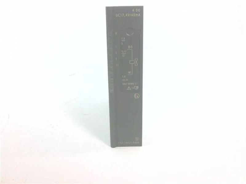
Siemens 6ES7132-7GD21-0AB0 — Digital Output Modules

6ES7132-7GD21-0AB0 ET200 DO 4ch 10.7VDC, Ex-i

MPN6ES7132-7GD21-0AB0
Active

Siemens SIMATIC ET 200 digital output module, 4 transistor channels plus 1 intrinsically-safe input, rated DC 10.7 V at 0.04 A, order code 6ES7132-7GD21-0AB0.

$361.95 – $741.00Ref. price · indicative, final on quote
Sourced new & surplus through independent channelsAuthenticity-screened · ESD-safe packingListing updated Aug 2026

Specifications

6ES7132-7GD21-0AB0 — Outputs
ParameterValue
Digital outputs4; additionally 1 intrinsically-safe input for L shutdown
Output typeTransistor
6ES7132-7GD21-0AB0 — Electrical
ParameterValue
Output current, resistive load, max.100 Hz
Output current at signal "1" (rated)0.04 A
Power dissipation (typ.)2.8 W
Isolation between channelsNo
Isolation between channels and backplane busYes
6ES7132-7GD21-0AB0 — Protection & Diagnostics
ParameterValue
Short-circuit protectionYes
Diagnostics functionYes
Diagnostic alarmYes; Parameterizable
Short-circuit detectionYes; R< 80 Ohm (one output), R< 40 Ohm (outputs connected in parallel)
Wire-break detectionYes; R > 10 kohms, I < 100 µA
6ES7132-7GD21-0AB0 — Performance
ParameterValue
Output switching delay 0 to 1, max.2 ms
Output switching delay 1 to 0, max.1.5 ms
Switching frequency, inductive load, max.2 Hz
6ES7132-7GD21-0AB0 — Mechanical & Connection
ParameterValue
Cable length, unshielded, max.500 m
Cable length, shielded, max.500 m
Width30 mm
Height129 mm
Depth136.5 mm
Weight (approx.)255 g

Product details

The 6ES7132-7GD21-0AB0: Channel logic sits at DC 10.7 V rated, with a signal '1' carrying 0.04 A per channel; no-load voltage Uao reads 17.4 V and the maximum Uo climbs to 19.4 V, which is the figure that feeds the Ex-i entity check on the field side.

Entity parameters for the hazardous-area side list Io at 118 mA maximum, Co at 241 nF for IIC groups and 1507 nF for IIB, and channel-to-channel isolation held at 60 V DC / 30 V AC — these three numbers are what the Ex-i loop designer cross-checks before a solenoid or indicator lands on the channel.

Diagnostics and backplane behavior

Wire-break detection trips when R > 10 kΩ with I < 100 µA; short-circuit detection engages at R < 80 Ω on a single output or R < 40 Ω with outputs paralleled — both diagnostics are parameterizable and surface through the SF (group error) LED and per-channel green status indicators. Backplane draw sits at 380 mA typical with 2.8 W typical power dissipation; address space is 2 bytes per module, which is the slot width the head allocates when this slice is configured into the station. Galvanic separation is provided between the channels and the backplane bus and between the channels and load voltage L+, but not between the channels themselves — that drives how multi-channel field returns are wired.

Cable runs and practical headroom

Both shielded and unshielded runs are rated to 500 m maximum on this module, so cable choices inside a skid or across a hazardous-area junction are not the limiting factor — the field device loop impedance is. Per-channel power output Po maxes at 572 mW against an internal series resistance Ri of 167 Ω, which sets the headroom for valve solenoid budgeting on each channel.

Lifecycle and spares posture

Lifecycle stage reads 'current' on the spec sheet — this is a BOM line that still has a factory behind it, which is what the critical-spare buyer wants to hear before putting one in the cabinet before it fails. CE marking is present; hazardous-area use relies on the Ex-i entity numbers above rather than a separate UL/IECEx certificate listed on this row.

Frequently asked questions

How many outputs and what voltage class?

4 transistor digital outputs plus 1 intrinsically-safe input for L shutdown, rated DC 10.7 V at 0.04 A per channel.

What are the Ex-i entity parameters?

Uo max 19.4 V, Io max 118 mA, Co 241 nF for IIC and 1507 nF for IIB — the three numbers that gate field-device selection.

What switching speed can the outputs deliver on inductive loads?

100 Hz on a resistive load drops to 2 Hz maximum on an inductive load — the inductive figure is the one that governs solenoid valves.

MPN
6ES7132-7GD21-0AB0