Module identity and I/O footprint
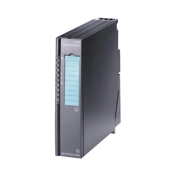
The Siemens 6ES7132-7RD22-0AB0 is an ET 200S distributed I/O digital output module: four transistor outputs and one additional intrinsically-safe input reserved for an H shutdown function, mounted on the SIMATIC DP backplane as a 30 mm slice. Each output is rated 0.04 A at 10.7 V DC, and two outputs may be paralleled on a single channel group to draw 80 mA from the same load-voltage rail — useful when driving a higher-current valve coil or a paired indicator loop within the IS boundary. The four outputs share a common load-voltage L+; channels are isolated from the backplane bus and from L+, but not from each other within a group, so the wiring diagram has to treat paired channels as one potential. Lifecycle stage on this order code is current per the spec row, which means the part is still specified into new SIMATIC DP stations and remains a live BOM line rather than a last-time-buy.
Intrinsically-safe output stage
The output stage is designed for hazardous-area field devices, with Uo capped at 19.4 V, Io at 118 mA, internal resistance Ri of 167 Ω, and Po at 572 mW — the same set of limits an integrator cross-checks against the Ex certificate of the field valve or indicator being driven. Permissible external capacitance Co is 241 nF for Group IIC installations and 1507 nF for Group IIB, so cable runs plus device input capacitance must be summed against the right group figure before the loop is accepted. Shielded and unshielded field cables are both listed to a maximum of 500 m, which is the practical field-cable length ceiling on a hazardous-area segment terminated to this module.
Switching behavior and timing
With inductive loads the maximum switching frequency drops to 2 Hz — anything faster on a coil has to be checked against the de-rating curve, not the headline 100 Hz figure.
Diagnostics, faults, and field-side monitoring
The module detects both short-circuit and wire-break on the field loop, with wire-break declared above 10 kΩ / below 100 µA and short-circuit flagged at less than 80 Ω on a single output or less than 40 Ω when two outputs are paralleled, and a parameterizable diagnostic alarm surfaces the event on the group-error SF LED. Per-channel green status LEDs give the on-site electrician a channel-level view without opening the diagnostic buffer, and the diagnostic information is also readable over the backplane for HMI-side trending. The module is not classified to SIL per the spec row, so a separate SIL-rated path is required for any safety function.
Power budget and mechanical envelope
Typical current consumption from the backplane is 380 mA, and the load-voltage L+ feed can draw up to 400 mA from the segment supply when the outputs are idle; typical power dissipation inside the module is 2.8 W, so the station power budget should leave headroom for neighboring slices. The module carries a CE mark, which covers the EU declaration of conformity for the assembled station.
Sourcing and station context
Because the lifecycle stage reads current, this order code is the one to specify into a new ET 200S station rather than reaching for a phased-out alternative; the spec row also flags it as suitable for uprating, which matters when the panel is being re-validated for a higher-horsepower downstream device. For the integrator assembling an ET 200S station, address space per module tops out at 2 byte, which is consistent with a four-output slice plus the one H-shutdown input, and the whole slice is configured through the standard ET 200S parameterization — no extra GSD file work is implied beyond the normal station bring-up. For procurement, this is a live BOM line; request a quote against the exact 6ES7132-7RD22-0AB0 order code so the station configuration and hazardous-area loop calculations stay matched to the as-installed hardware.