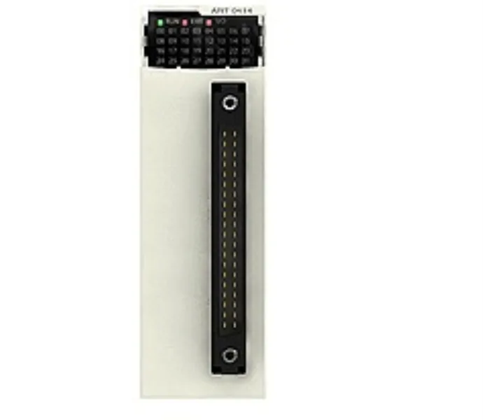
What lands in the rack
The BMXART0414: Each channel lands on a 40-way front connector and is galvanically isolated from the backplane at 1400 V DC and from adjacent channels and ground at 750 V DC, which lets one module span thermocouple zones that would otherwise demand a barrier — useful when mixing a grounded-junction probe with a floating one on the same rack. Conversion is a 16-bit sigma-delta ADC presented to the application as 15 bits + sign; nominal read cycle time is 400 ms with an RTD and 200 ms with a thermocouple, which is the figure to plan against for a control loop rather than the headline channel count.
Where the numbers actually decide the fit
Measurement error is the spec a thermocouple panel really gets judged on: at a 25 °C reference the module reads Ni 1000 to ±0.7 °C, Pt 100 / Pt 1000 / Ni 100 to ±2 °C, thermocouple R/S to ±3.2 °C, and thermocouple K/N/E/T to ±3.7 °C; widened to the 0…60 °C operating span those figures roughly double (e.g. Pt 100 / Pt 1000 ±2 °C → ±2 °C, but thermocouple B climbs from ±3.5 °C to ±5 °C). Cold-junction compensation is handled externally via a Pt100 probe. Temperature drift sits at 25 ppm/°C for the RTD ranges and most thermocouples, and 30 ppm/°C for the mV ranges and the higher-resistance Pt/Ni probes, so warm-cabinet derating is small but non-zero across long cable runs. Common-mode rejection is 120 dB at 50/60 Hz and differential-mode rejection 60 dB at the same frequencies, with permitted overload on every voltage input of ±7.5 V — the ruggedness margin an integrator wants when field wiring comes from a noisy plant. Maximum wiring resistance is 200 Ohm 2-wire / 3-wire for Ni 1000 and Pt 1000, 500 Ohm 4-wire for the same, and 20 Ohm / 50 Ohm for the lower-resistance probes — the limit that decides whether you can run a 4-wire Pt100 across a long conduit or have to step to the high-resistance Pt 1000.
Backplane budget and panel placement
The module draws 150 mA at 3.3 V DC and 40 mA at 24 V DC from the X80 rack, which is the figure to carry into a backplane power calculation when the rack already holds discrete I/O or fast analog outputs; the IP20 housing and 0…60 °C operating envelope match the rest of the Modicon X80 family, with shock 30 gn, vibration 3 gn, and 5…95 % RH non-condensing at 55 °C. Above 2000 m the module can still operate up to 5000 m with a derating factor applied per the Modicon X80 system manual, and storage tolerates −40…85 °C so handling and staging in a panel shop is unconstrained. Front-panel indicators are one green RUN LED, one green per-channel diagnostic LED, a red ERR LED, and a red I/O LED — enough granularity to fault-isolate a single open thermocouple from the rack without pulling the module. Resolution is 0.1 °C across every thermocouple and RTD type, and per-range on the voltage inputs (e.g. 40/2^14 mV on the ±40 mV range, 12.5 mΩ on the 400 Ohm range), with first-order digital filtering on the input stage.
Compliance declaration
The module is declared against IEC 61131-2, IEC 61000-6-4, and IEC 61000-6-2, and meets EN 61010-2-201, with the EU declarations covering 2014/35/EU (low voltage) and 2014/30/EU (electromagnetic compatibility) — the standard set a process skid or a panel destined for an EU line expects to see on the decl pack. MTBF is rated at 1,400,000 H, which for spares planning reads as a long-life component rather than a wear item.