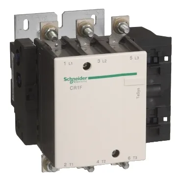
The magnetic latching mechanism holds the contacts closed without continuous coil power, which is the key difference from a standard contactor: the coil only needs a pulse to latch or unlatch, cutting steady-state power draw and heat in the panel. Rated operational voltage goes to 1000 V AC, 25–200 Hz, so it handles 400 V and 690 V lineups without a problem. Motor power capability spans the voltage range: 160 kW at 690 V AC, 147 kW at 1000 V AC, down to 75 kW at 220–230 V AC. Under UL/CSA, it carries 175 hp at 575–600 V. The conventional free-air thermal current (Ith) is 350 A at 40 °C, which gives the continuous current rating for resistive loads in AC-1 duty.
Coil and control circuit — the latching logic
The control circuit accepts two separate voltages: 220 V AC (50/60 Hz or 400 Hz) for the latching coil, and 24 V AC/DC for the unlatching coil. This dual-voltage arrangement is specific to the magnetic latching design — you apply 220 V to latch the contacts, and 24 V to release them. The operating time is 45–50 ms to latch, 50–100 ms to unlatch. Coil consumption peaks at 1650 VA (AC, latching) or 1800 W (DC, latching), but drops to 9 VA / 12 W for the unlatching pulse. That means the 220 V latching coil will operate reliably down to 187 V and up to 242 V; the 24 V unlatching coil works from 20.4 V to 26.4 V. If your control supply sits outside that band, you'll need to regulate it.
Where you'd use this — deployment context
This is a panel-mount contactor — it bolts into a switchboard or motor control center, not a DIN rail. The terminal connections accept lugs or ring terminals (up to 240 mm² per cable), connectors, or busbars up to 32 x 4 mm. Tightening torque is 35 N·m on the power terminals, so you'll want a torque wrench for the M10 or equivalent studs. The dimensions are 203 mm high, 201.5 mm wide, and 213 mm deep — factor that into your enclosure layout, especially the depth for cable bending radius behind the panel. Storage range is -60 °C to 80 °C. The protective treatment is TH (tropicalized, humidity-resistant), so it's suited for non-condensing environments with moderate humidity.
Breaking capacity and fault handling
The rated breaking capacity varies by voltage: 2450 A at 220–440 V, 2200 A at 500 V, 1700 A at 660/690 V, and 800 A at 1000 V. The rated making capacity (Irms) is 2940 A. For short-time withstand, the Icw ratings are 2200 A for 1 second, 2200 A for 5 seconds, and down to 480 A for 10 minutes — these tell you how long the contactor can carry fault current before the upstream protection needs to clear. Associated fuse recommendations are 315 A aM, or 400 A gG/BS88 at ≤ 440 V. Mechanical durability is rated at 1 million cycles. Maximum operating rate is 120 cycles per hour at 40 °C. Power dissipation per pole runs 22 W in AC-3 duty and 39 W in AC-1 — that's about 66 W total for AC-3, 117 W for AC-1, so factor that into your panel cooling if you're cycling near the max rate.