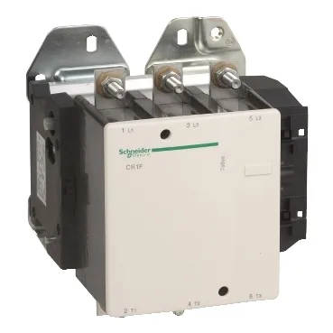
The CR1F500U7 is a 3-pole magnetic latching contactor from the TeSys F range, rated for 500 A in AC-4 duty at ≤440 V — that is the motor-switching category for reversing, plugging, and inching duty, where the contacts make and break full locked-rotor current. The 250 kW motor power at 400 V AC-4 per the datasheet gives a direct sizing reference for a 400 V induction motor under severe switching conditions. The latching mechanism holds the main contacts closed without sustained coil power; the coil draws 1650 VA during the latching pulse and only 9.5 VA to hold the unlatching coil ready, so the control transformer sizing is driven by the pulse, not the steady state.
Control circuit and coil behaviour
The coil is 240 V AC 50/60 Hz, with a latching voltage tolerance of 0.85 to 1.1 Uc — so it must see at least 204 V to pull in reliably. The unlatching coil has the same tolerance range. Operating time is 40-80 ms to latch and 50-100 ms to unlatch; that matters for sequencing interlocks where the contactor must open before a reversing contactor closes. The average impedance of 0.18 mOhm at 700 A Ith (thermal current) is the per-pole resistance used to calculate I²R heating in the panel.
Mounting and connection
Power circuit connections are bolted lugs or ring terminals up to 240 mm², or bars 40 x 5 mm. The tightening torque is 35 N·m — a torque wrench is required, not a hand driver. The contactor occupies a 232 mm depth, 233 mm width, and 238 mm height footprint; it is a panel-mounted device, not DIN-rail snap-on, so the enclosure backplate must be drilled for the mounting holes.
Short-circuit and withstand ratings
The rated short-time withstand current (Icw) is 4200 A for 1, 5, and 10 seconds at 40 °C, tapering to 1200 A for 10 minutes. That means the contactor can carry these fault currents for the stated durations without damage — useful for selective coordination studies. The associated fuse ratings are 500 A aM or 800 A BS88/gG at ≤440 V; the fuse must clear before the contactor's Icw limit is exceeded.