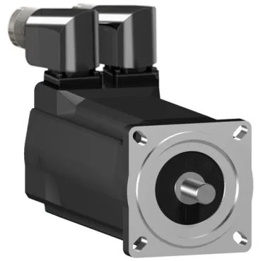
Motor form factor and mounting interface
The SH30702M12F2000 is a 70 mm flange-size servo motor (2.8 in) with an international standard flange mounting, centring collar diameter 60 mm (2.4 in) and depth 2.5 mm (0.10 in). Overall length is 212.5 mm (8.4 in); the shaft is 11 mm diameter with a parallel key, 23 mm shaft length, and 4 mm key width — this matches the standard SH3 frame envelope for direct coupling to ball screws or timing-belt pulleys.
Speed-torque envelope across supply voltages
Nominal speed varies by supply: 750 rpm on 115 V single-phase, 1500 rpm on 230 V single-phase, 3000 rpm on 400 V three-phase, and 3600 rpm on 480 V three-phase — the motor is wound for multi-voltage operation, so the same unit can be configured for different line voltages by changing the drive parameters. Nominal torque is 2.2 N·m (19.5 lbf·in) at 115 V single-phase, 2.15 N·m (19.03 lbf·in) at 230 V single-phase, and 2.03 N·m (17.97 lbf·in) at both 400 V and 480 V three-phase — torque drops slightly at higher voltages as the motor reaches its thermal limit at the higher speed. Continuous stall torque is 2.04 N·m (18.06 lbf·in) across the 115–480 V three-phase range, with a continuous stall current of 1.5 A — this is the torque available at zero speed for holding or positioning without exceeding the winding temperature rating. Peak stall torque reaches 7.6 N·m (67.3 lbf·in) on three-phase supplies — this is the short-duration overload capability for acceleration or overcoming static friction, not continuous duty.
Brake and encoder for holding and feedback
The integrated holding brake delivers 3 N·m (26.6 lbf·in) holding torque — sufficient to hold the load on a vertical axis without power, eliminating the need for an external brake resistor or mechanical lock. Feedback is via an absolute multiturn SinCos Hiperface encoder — this provides position data at power-up without a homing cycle, and the multiturn count tracks absolute position over multiple shaft revolutions, which is critical for tool-change or pallet-transfer applications where the home position must be retained after a power loss.
Environmental sealing and cooling
The motor carries dual IP ratings per IEC 60034-5: IP54 at the shaft bushing without the shaft seal ring, and IP65 at the motor body and shaft bushing when the seal ring is fitted — the IP65 configuration is suitable for washdown environments where coolant mist or light spray is present, while IP54 is acceptable for dry indoor machine-tool enclosures. Cooling is by natural convection — no external fan or forced air is required, which simplifies installation in confined spaces but means the continuous torque rating assumes free airflow around the motor housing; derating applies if mounted in a confined pocket without ventilation.
Electrical parameters for drive tuning
Stator resistance is 16.4 Ω and stator inductance is 115.7 mH — these values are used by the servo drive's autotuning routine to set current-loop gains; the relatively high inductance means the motor is well-suited to low-ripple current control at moderate switching frequencies. Torque constant is 1.36 N·m/A at 120 °C copper temperature, and the back-EMF constant is 95.9 V/krpm at 20 °C — these define the relationship between current and torque, and between speed and voltage, respectively, and are needed for the drive's velocity-loop tuning. Maximum current is 6 A RMS — this is the drive's peak current limit setting; the continuous stall current of 1.5 A is the thermal limit for sustained operation.
Mechanical load limits and speed ceiling
Maximum mechanical speed is 8000 rpm — this is the bearing and rotor structural limit, not the rated operating speed; the motor can be oversped above the nominal 3000–3600 rpm range for brief periods if the load inertia is low and the drive limits acceleration. Maximum radial force Fr is load-dependent: 710 N at 1000 rpm, decreasing to 390 N at 6000 rpm — this is the allowable side load on the shaft from belt tension or gear mesh, and must be checked against the application's bearing life target. Maximum axial force Fa is 80 N — this is the allowable thrust load on the shaft, relevant for direct-drive leadscrew applications where the motor bearings carry the axial load.