What It Is and Where It Fits
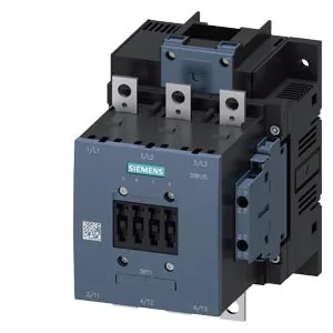
The Siemens SIRIUS 3RT1055-6AU36 is a size S6 power contactor, designed for switching motor loads and resistive loads in industrial control panels. It's part of the SIRIUS modular contactor family, which means it integrates with the same SIRIUS accessory ecosystem for overload relays, suppressors, and busbar systems. The contactor measures 172 mm high by 120 mm wide by 170 mm deep, and mounts via screw fixing to a vertical surface. The mounting position allows +/-90° rotation and +/-22.5° tilt forward/back, so you can orient it to fit tight panel layouts without derating. It carries a 240-277 V AC coil, with a pickup threshold of 0.8 x rated voltage at both 50 Hz and 60 Hz, and a dropout threshold of 0.8 x rated voltage. The full-scale operating range extends to 1.1 x rated voltage, so it holds in on a stiff 277 V line without saturation issues.
Key Ratings and What They Mean for the Line
The operating times are deterministic: 40-60 ms for both AC and DC coil pickup, and 10-15 ms arcing time. That's a tight window for a contactor this size — it holds takt time on a weld line where every cycle is gated by the main contactor's dropout. The mechanical endurance is 10,000,000 operations typical, which translates to years of service at 750 cycles/hour under AC-3 duty. Switching frequency varies by duty class: 800 cycles/hour at AC-1 (resistive), 750 cycles/hour at AC-3 (motor start/run), and 130 cycles/hour at AC-4 (plugging/inching). If your application involves frequent reversing or jogging, the AC-4 limit is the one that governs — exceeding it will overheat the arc chamber. The main power circuit accepts stranded conductors from 25 to 120 mm², which covers everything from a 35 mm² motor feed to a 95 mm² busbar tap. The auxiliary circuit uses screw-type terminals accepting 2x (0.5-1.5 mm²) solid or 2x (0.75-2.5 mm²) stranded, with a max of 2x (0.75-4 mm²). That's enough for two parallel 1.5 mm² control wires per terminal. The built-in auxiliary switch is rated 10 A at 24 V, 2 A at 48 V and 60 V, and 1 A at 110 V. Those are the current-carrying limits for the auxiliary contacts — don't use them to switch the coil of a downstream contactor without checking the inrush against these ratings.
Integration and Panel Layout
Clearance distances are specified: 10 mm upwards, 10 mm downwards, 10 mm at the side, and 20 mm forwards. These are the minimum air gaps to adjacent metalwork or other devices — ignoring them can cause flashover during arc extinction. The mounting holes are 9 mm diameter, single hole per terminal, so use M8 bolts or studs. Operating temperature range is -25 to +60 °C, with storage from -55 to +80 °C. That covers most indoor panel environments, but if the contactor sits near a furnace or in a sun-baked enclosure, verify the internal panel temperature stays under 60 °C at full load.