What it is and where it fits
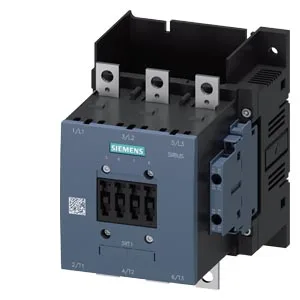
The Siemens 3RT1055-6LA06 is a SIRIUS power contactor in the size S6 frame — the largest standard contactor footprint in the SIRIUS family, intended for high-current motor switching and resistive loads in industrial control panels. It mounts via screw fixing on a vertical surface with ±90° rotation and ±22.5° tilt, so it adapts to tight enclosure layouts without a separate mounting plate.
Key ratings and what they mean for the buyer
The main circuit accepts stranded conductors from 25 to 120 mm², which covers motor feeds up to roughly 200 A depending on duty — the 230 V motor rating is 30 hp, a solid benchmark for a 30–40 kW motor at 400 V three-phase. The auxiliary contact block is rated at 10 A at 24 V and derates to 0.3 A at 230 V, so it can drive PLC inputs or small relays at control voltage but needs checking if you're switching a 230 V pilot light at the full 10 A — it won't. Mechanical endurance is 10 million operations typical, meaning this contactor is built for high-cycle applications like conveyor or pump stations that cycle several times per minute. Switching frequency varies by duty class: AC-1 (resistive) allows 800 operations per hour, AC-3 (squirrel-cage motor start/run) allows 750, and AC-4 (plugging/inching) drops to 130. That AC-3 figure is the one most buyers care about — 750 ops/h is enough for a fast cycling line but not for a servo-style reversing application. The arcing time is 10–15 ms, which is typical for a contactor this size and means the arc chute does its job without excessive contact wear. Operating temperature range is -25 to +60 °C, with storage from -55 to +80 °C. The 60 °C ceiling is fine for most indoor panels but marginal for a sun-baked enclosure in a Middle East plant — if ambient inside the panel hits 55 °C, you're still within spec but should derate the current per the manufacturer's curve (not included here).
Mounting and wiring notes
The contactor measures 172 mm high by 120 mm wide by 170 mm deep — that's a substantial footprint, so check your DIN-rail or backplate real estate before committing. Clearance requirements: 10 mm upwards and downwards, 20 mm forwards, 10 mm at the sides. The coil terminals are screw-type, and the auxiliary wiring accepts solid or stranded conductors: 2x 0.5–1.5 mm², 2x 0.75–2.5 mm², or max 2x 0.75–4 mm². That covers standard control wiring but won't accept a single 6 mm² — plan your terminal blocks accordingly.