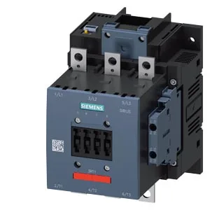
It uses a 200-277 V AC coil and mounts via screw fixing, not DIN rail — so plan for a drilled backplate or mounting rail with 9 mm holes on a 120 mm width footprint.
This contactor is built for high switching frequencies: up to 800 operations per hour in AC-1 (resistive) duty, 750 in AC-3 (motor start/run), and 130 in AC-4 (plugging/inching). The AC-3e rating matches AC-3 at 750 ops/h, so it handles frequent motor starts without derating the coil. Coil pick-up and drop-out times are 80-90 ms on both AC and DC supplies, with arcing time between 10-15 ms. That means predictable contact closure timing for sequencing logic — useful when coordinating with upstream breakers or downstream auxiliaries. The auxiliary switch (built-in) handles 10 A at 24 V, 2 A at 48 V and 60 V, and 1 A at 110 V — enough for direct PLC input or relay coil drive without an interposing relay.
Wiring and integration details
Main power terminals accept stranded cable from 25 to 120 mm² — that's a serious lug range for a size S6 frame, covering motor feeds up to roughly 200 A depending on duty. The coil uses screw-type terminals, not spring-cage, so expect to torque down properly. Auxiliary wiring is via solid or stranded conductors: 2x 0.5-1.5 mm², 2x 0.75-2.5 mm², or max 2x 0.75-4 mm² per terminal. Keep the smaller gauge for signal-level aux circuits and the larger for interposing relays. That 20 mm forward clearance is often the one people miss when panel depth is tight.
For a BOM freeze or compliance audit, expect standard Siemens documentation: CE declaration, RoHS and REACH statements, and UL/CSA file numbers per the contactor family. No special PCN risk here.