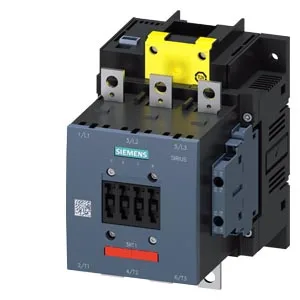
It carries a coil rated at 96-127 V AC, with screw-type coil terminals and an integrated auxiliary switch. Rated mechanical endurance is 10,000,000 cycles typical, with an MTBF of 75 a.
Switching frequency varies by duty class: AC-1 (resistive) and AC-3 (motor start/run) both allow up to 750 operations per hour, AC-2 (slip-ring motor) also 300/h, and AC-4 (plugging/inching) drops to 130/h. The AC-3e maximum matches the standard AC-3 rate at 750/h. These rates define the thermal cycling the contactor can sustain without accelerated wear — a conveyor running frequent start/stop cycles at 750/h stays within the AC-3 envelope. Operate time is 115-130 ms on both AC and DC coils, with an arcing time of 10-15 ms. The coil pickup threshold is 0.8 × rated voltage, dropout at 0.6 × rated (50/60 Hz). These figures matter for control logic timing and for ensuring the contactor holds in during voltage sags. Auxiliary contact ratings: 10 A at 24 V, 2 A at 48 V, 2 A at 60 V.
Envelope dimensions: 172 mm high × 120 mm wide × 170 mm deep. Mounting is screw-fixing to a vertical surface; the contactor can be rotated ±90° and tilted ±22.5° front-to-back. These clearances govern gland-plate layout and busbar routing — a 120 mm wide contactor with side clearance needs roughly 140 mm of DIN-rail or backplate width per unit. Main power terminals accept stranded 25-120 mm² cable. Auxiliary terminals accept 2× (0.5-1.5 mm²), 2× (0.75-2.5 mm²), or max 2× (0.75-4 mm²) solid or stranded. The coil uses screw-type terminals — no push-in or spring-cage on the coil circuit. Panel builders should plan for a screwdriver-accessible coil connection.
Sourcing is straightforward: this is a current-catalog SIRIUS contactor. The part is quoted to order through independent distribution — no minimum-buy or long-lead concern typical of end-of-life parts.