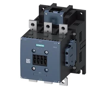
S10 frame, 110 VDC coil, screw-fixed
The 3RT1065-6XF46-0LA2: It comes with a fitted auxiliary switch block and is fixed by screw mounting, not DIN-rail snap-on. This means the contactor drops out cleanly at about 77 V, avoiding nuisance drop-out on a sagging 110 VDC bus.
Panel fit and mechanical endurance
The contactor measures 202 mm deep, 145 mm wide, and 210 mm high. The mounting plate needs four clearance holes — one 11 mm diameter hole per corner — for the screw fixings. Mounting position is flexible: the contactor can be mounted on a vertical surface and rotated ±90°, or tilted forward/backward ±22.5°, which helps when fitting into tight or angled enclosure backplates.
Wire termination and duty cycle limits
This covers most standard motor feeder cables up to about 12 AWG. Switching frequency limits vary by duty class: 700 operations per hour in AC-1 (resistive), 500 per hour in AC-3 (squirrel-cage motor starting), and 130 per hour in AC-4 (plugging/inching). For DC loads, the limit is 350 per hour across DC-1, DC-3, and DC-5. These numbers set the maximum cycling rate for the application; exceeding them risks contact welding or overheating.
Auxiliary contact DC ratings
These are the maximum continuous currents the auxiliary contacts can break in DC circuits; inductive loads (relays, solenoids) should be derated further or fitted with a flyback diode.